Tennessee Department of Transportation
Survey & Design
COMPUTER-AIDED
DRAFTING & DESIGN
STANDARDS

All correspondence to TDOT CADD Support should be addressed to:
Tennessee Department of Transportation
Design Division
CADD Support
Suite 1300 James K. Polk Building
Nashville, TN 37243-0348
Introduction 1
readability or appearance: 35
TDOTxsection.dgnlib 77
Introduction
This manual shall be used as the standard for all computer aided drafted and designed plans development produced by and for the Design Division of the Tennessee Department of Transportation.
Survey submissions shall be in accordance with this manual and/or modifications contained in the consultant’s contract or as prescribed by the Regional SurveySupervisor.
Standard Parameters
In order to establish standard parameters by which drawings are to be created, the following parameters have been established:
- 1.
- Accuracy Control through working units and resolution providing state widecoverage of the state coordinate system on a design plane. This provides directcorrelation of design data point input to the coordinate plane reference point.
- 2.
- Standard level, color, and weight assignments of design elements assigned according to the type of sheet being generated.
- 3.
- Standard level names and text styles established through design file level libraries TDOTmain.dgnlib & TDOTxsection.dgnlib.
- 4.
- Cell development of over 1100 cells relating to design elements, signing, sheet generation, etc. The standard cell libraries are STDS.CEL & SIGN.CEL for English-unit projects and METRIC.CEL & MSIGN.CEL for metric projects.
- 5.
- Custom line style development of over 500 line styles in resource file TDOTLINE.rsc for standardized display of linear design elements.
- 6.
- Standard color table STDCOLOR.TBL for standardized display of color codeddesign elements.
Standard File Extensions
The following table lists the TDOT standard file extensions. In order to provide
consistency with TDOT standard programs, these extensions shall be used with all
Survey and Design files.
.CEL Cell Library
.DGN Project Graphics Design File.
.SHT Project Sheet Graphics Design File
.DGNLIB DGN Level & Text Style Library File.
.GPK Geopak Coordinate Geometry Database
.TIN Geopak Digital Terrain Model File
.RSC miscellaneous Resource File.
.TBL Features, Color, etc., Table.
.TXT ASCII Text File.
Standard Filenames
All graphical information is to be drawn at actual size at it's corresponding state plane coordinate location. Only text and symbols( MicroStation cells) are scaled to appear correctly when plotted.
Survey DGN Project Filenames
The project’s Survey DGN filename will consist of the two-digit county abbreviation, three-digit Project Route, the GPS project number and the file type. All files should use a .DGN extension.
No spaces or extra periods should be used in any filename.
The following is a more detailed explanation of the standard Survey DGN filename:
11222-33FileType.DGN
The filename shall consist of the following parts:
| 11 | two (2) letters to identify the project county location.(see county listing at the end of this section) |
| 222 | three (3) numbers to identify the project route. |
| -33 | dash + two (2) numbers to identify the GPS project number. |
| FileType | file type as described below |
| DGN | standard file extension. |
Survey Project File Types:
Survey Survey Topography and Profile dataExample: DV155-01Survey.DGN
SurveySUE Survey Subsurface Utility Engineering dataExample: DV155-01SurveySUE.DGN
Design DGN Project Filenames
The project’s Design DGN filenames will consist of the two-digit county abbreviation, the road name, and the file type name. All files should use a .DGN extension except for sheet files which should have .SHT for the extension.
For plan sheet files other than cross sections, the filename shall consist of the sheet number only. Sheet numbers should include “0” prefixes as needed to ensure alphabetic sorting (Example for sheet 9A: 009A.SHT).
No spaces or extra periods should be used in any filename.
The following is a more detailed explanation of the standard Design DGN filename:
CoRoadnameFileType.DGN
The filename shall consist of the following parts:
| Co | two (2) letters to identify the project county location.(see county listing at the end of this section) |
| Roadname | Alphanumeric to identify the state route number or road name if not a state route. |
| FileType | file type as described below |
| DGN | standard file extension (SHT for all plans sheets) |
Design Project File Types:
Alignments Proposed Horizontal & Vertical alignment data Example: DVSR155Alignments.DGN
Proposed Proposed Horizontal & Vertical data other than alignments. Example: DVSR155Proposed.DGN
PropertyMap Property Map dataExample: DVSR155PropertyMap.DGN.
TrafficControl Traffic Control data Example: DVSR155TrafficControl.DGN
ErosionControl Erosion Control data Example: DVSR155ErosionControl.DGN
ExistingContours Existing Contour dataExample: DVSR155ExistingContours.DGN
DrainageMap Drainage Map dataExample: DVSR155DrainageMap.DGN
ProposedContours Proposed Contour dataExample: DVSR155ProposedContours.DGN
3
| SEShapes | Proposed GEOPAK superelevation shapesExample: DVSR155SEShapes .DGN |
| Signalization | Proposed Intersection Signalization dataExample: DVSR155Signalization.DGNNOTE: File in which all signalization work for intersections on the project will be done. |
| Utilities | Proposed Utilities dataExample: DVSR155Utilities.DGN |
GEOPAK Pattern File Types:
| RoadwayPattern | Roadway Cross Section pattern linesIncludes mainline & side road pattern lines with a different symbology for each roadway. Example: DVSR155RoadwayPattern.DGN. |
| CulvertPattern | Culvert Cross Section pattern linesExample: DVSR155CulvertPattern.DGN. |
| PvtDrivePattern | Private drive pattern linesExample: DVSR155PvtDrivePattern.DGN. |
GEOPAK Cross Section File Types: (Use seed file SEEDXS.DGN)
roadwayXSections
CulvertXSections PvtDriveProfiles
Standard Sheet File Types: (Use .SHT extension)
sht#
roadwayXSections
roadwayCulvertXSections
Roadway Cross Section data. Substitute a specific name for
roadway, mainline or side road. Each roadway’s cross
sections will be in a separate DGN file.
Example: DVSR155MainlineXSections.DGN.
Culvert Cross Section data
Example: DVSR155CulvertXSections.DGN.
Private drive profile data
Example: DVSR155PvtDriveProfiles.DGN.
All plan sheets, one sheet per file, sheet number only
Examples: Sheet 4 > 004.SHT , Sheet 4A > 004A.SHT Sheet 24 > 024.SHT Sheet 24A > 024A.SHT
Roadway Cross Section sheets. Substitute a specific name
for roadway, mainline or side road. Each roadway’s cross
section sheets will be in a separate DGN file.
Example: SR155XSections.SHT
Culvert Cross Section sheets.
Example: SR155CulvertXSections.SHT
4
| Number | County | |
|---|---|---|
| AN | Anderson | |
| BD | Bedford | |
| BN | Benton | |
| BS | Bledsoe | |
| BT | Blount | |
| BR CM CN | Bradley Campbell Cannon | |
| CA | Carroll | |
| CR | Carter | |
| CT | Cheatham | |
| CH | Chester | |
| CB | Claiborne | |
| CL CO | Clay Cocke | |
| CF | Coffee | |
| CK | Crockett | |
| CU | Cumberland | |
| DV | Davidson | |
| DE | Decatur | |
| DK | DeKalb | |
| DS | Dickson | |
| DY FA FE | Dyer Fayette Fentress | |
| FR | Franklin | |
| GB | Gibson | |
| GI | Giles | |
| GG GR | Grainger Greene | |
| GD HB | Grundy Hamblen | |
| HT | Hamilton | |
| HC | Hancock | |
| HM | Hardeman | |
| HD | Hardin | |
| HK | Hawkins | |
| HW HS | Haywood Henderson | |
| HY HI | Henry Hickman | |
| HO | Houston | |
| HU JK | Humphreys Jackson | |
| JF | Jefferson | |
| JN | Johnson | |
| KN | Knox | |
| LA | Lake |
Number County
| 49 | LD | Lauderdale |
| 50 | LW | Lawrence |
| 51 | LE | Lewis |
| 52 | LI | Lincoln |
| 53 | LO | Loudon |
| 54 | MM | McMinn |
| 55 | MN | McNairy |
| 56 | MC | Macon |
| 57 | MD | Madison |
| 58 | MA | Marion |
| 59 | MS | Marshall |
| 60 | MU | Maury |
| 61 | ME | Meigs |
| 62 | MR | Monroe |
| 63 | MT | Montgomery |
| 64 | MO | Moore |
| 65 | MG | Morgan |
| 66 | OB | Obion |
| 67 | OV | Overton |
| 68 | PE | Perry |
| 69 | PI | Pickett |
| 70 | PO | Polk |
| 71 | PU | Putnam |
| 72 | RH | Rhea |
| 73 | RO | Roane |
| 74 | RB | Robertson |
| 75 | RF | Rutherford |
| 76 | SC | Scott |
| 77 | SQ | Sequatchie |
| 78 | SE | Sevier |
| 79 | SH | Shelby |
| 80 | SM | Smith |
| 81 | ST | Stewart |
| 82 | SL | Sullivan |
| 83 | SU | Sumner |
| 84 | TI | Tipton |
| 85 | TR | Trousdale |
| 86 | UC | Unicoi |
| 87 | UN | Union |
| 88 | VB | Van Buren |
| 89 | WR | Warren |
| 90 | WS | Washington |
| 91 | WA | Wayne |
| 92 | WE | Weakley |
| 93 | WH | White |
| 94 | WM | Williamson |
| 95 | WI | Wilson |
Data Exchange between Survey & Design Personnel
At different points in a project's life prior to submittal for construction certain files will be created, used and appended to by both Survey & Design personnel.
These files include:
Geopak GPK coordinate/geometric database
MicroStation DGN topography graphics
Geopak TIN digital terrain model
With this in mind the following procedures shall be followed.
GPK Naming Conventions
GPK files shall be named with the project Region number plus an alphanumeric job number assigned by the Regional Survey Supervisor. Example: For a Geopak project inRegion 2 ... job2p4.gpk
All points, curves & spirals shall be created with a specific alpha prefix plus any otherletters or numbers desired by the user. This procedure must be followed in order to prevent overwriting previously stored data.
The following prefixes will be used to name all points and curves stored in the GPK file:
Division Prefix Point Example Curve Example Spiral ExampleSurvey S S105 SC105 SC105A Design D D105 DC105 DC105A
Chain & Profile names shall be named using a descriptive form (such as the road name) so that it can be easily distinguishable by all personnel.
Design personnel should maintain the names of chains that are associated with the exist. R.O.W. flags whenever possible in order to minimize update time as alignments are adjusted.
These chain names can be up to a maximum of 8 characters. (Examples: SR95, Campbell).
Groundline profiles should include the letters GRN in their names such as SR95GRN or CampGRN.
NOTE:
In order to prevent accidental overwriting of data it is recommended that all users work with the Redefine option clicked off in Geopak Cogo until you need tomake a change and only then go and click this option on temporarily.
Graphical Survey Data
All Survey graphics files shall be in 3D MicroStation DGN format. No DXF files, IGES files, or other translation files will be accepted.
Project Data Workflow
The following 2 sections describes the workflow in non-phased and phased projects. Projects not done in phases are described first since this is the way most projects are done. Additional information procedures are the same for either phased or not and is described following the phased project description
Non-Phased Project Data Workflow
by Survey personnel…
Topo Graphics
Digital Terrain Model
Cogo Database
by Design personnel…
Topo Graphics
Digital Terrain Model Cogo Database
*.DGN
*.TIN
*.GPK
*.DGN
*.TIN *.GPK
Field survey data is used to build 3D topographic DGN file. If aerial survey data is available then it is combined with field survey topo DGN for turn in version for Design.
Field survey data is used to build TIN file. If aerial survey data is available then it is combined with field survey TIN file for turn in version for Design.
Survey sets up initial GPK file for the project with all existing data including preliminary & existing alignments, topo, etc.
Adopt 3D topo DGN submitted by Survey. This file is the official Topo file for the project. Changes in label locations are done as needed to enhance plans appearance.
No changes are to be done.
Adopt GPK file submitted by Survey. This file is the official GPK file for the project. Further development is done as needed to complete project design.
Note concerning Preliminary centerlines: Once the GPK file is received from Survey, Design personnel should review preliminary centerline chains submitted by Survey for use as final proposed centerlines. If they need to be adjusted, the chain should first be saved under a different name for later reference as needed. Then the chain should be adjusted as required without being re-named. Once the centerline chains are set they can be displayed in the Design Alignments DGN file as proposed centerlines for inclusion in the plans. All alignments should be investigated completely before any additional information on a project is requested.
Phased Project Data Workflow
Final Scoping Report Phase
Aerial Mapping shall be used for preliminary alignment and grade studies. Preliminary alignment and grade will be included as part of Final Scoping Report (FSR) document for use in survey. Other Sections shall perform environmental and historical evaluations.
| by Design personnel… | ||
|---|---|---|
| Topo Graphics | *.DGN | Use 3D DGN submitted by Aerial Surveys for reference only. No changes are to be done. |
| Digital Terrain Model | *.TIN | Create temporary TIN file from DGN digital terrain model graphics file submitted by Aerial Surveys or with USGS DEM data for alignment investigation. |
| Cogo Database | *.GPK | In temporary GPK file, horizontal & vertical alignments are developed. These chains & profiles are then submitted to Survey in Geopak Cogo input files for inclusion in the official GPK file. |
| Phase 1 |
Under Phase 1, survey personnel will provide the designer with aerial mapping and minimal field survey information for preliminary design. Scanned Tax Map property information shall be used for preliminary property work. Designer shall calculate proposed horizontal and vertical alignments, and send them to survey section when complete.
by Survey personnel…
Topo Graphics
Digital Terrain Model
Cogo Database
by Design personnel…
Topo Graphics
Digital Terrain Model Cogo Database
*.DGN
*.TIN
*.GPK *.DGN *.TIN *.GPK
Aerial Mapping plus Survey Phase 1 Collections sent to Design when Phase 1 is complete as 3D file.
Original Model as compiled from Aerial Mapping and/or the Phase 1 Survey collections.
Created By Survey Division
Use 3D DGN submitted by Survey for reference only. No changes are to be done.
No changes are to be done.
In Phase 1 GPK file, horizontal & vertical alignments are developed. These chains & profiles are then submitted to Survey in Geopak Cogo input files for inclusion in the official GPK file.
8
Phase 2
Under Phase 2 survey will be completed on: property, existing right-of-way, drainage not included in Phase 1, and on utilities not included in Phase 1. Designer will begin plans development after receipt of Phase 2 survey.
by Survey personnel…
Topo Graphics
Digital Terrain Model
Cogo Database
by Design personnel…
Topo Graphics
Digital Terrain Model Cogo Database
*.DGN
*.TIN
*.GPK
*.DGN
*.TIN *.GPK
Survey Phase 1 *.DGN plus anything that has been added since Phase 1. Submit final 3D Topo file to Design.
Survey Phase 1 *.tin plus any changes that have been updated since the Phase 1 submittal.
Survey Phase 1 *.GPK plus alignments entered by using input files, as well as any additional data collected and processed by the surveyor since the Phase 1 submittal.
Adopt final 3D version of Phase 2 DGN submitted by Survey. This file is official Topo file for the project. Changes in label locations are done as needed to enhance plans appearance.
No changes are to be done.
In Phase 2 GPK file submitted by Survey, further development is done as needed to complete project design.
Additional Information
Submitting Additional Information Request
by Design personnel…
Topo Graphics *.DGN Submit current Topo DGN and alignments DGN file with documentation of additional Topo and/or digital terrain model information needed. Documentation may take the form of typed information in letter or email or notes in DGN file or on plots. No changes are to be done in Topo file from this point until received back from Survey.
Digital Terrain Model *.TIN No changes are to be done.
Cogo Database *.GPK In project GPK file further development is done as needed to continue project design. When alignment changes have been done, new information is sent to Survey using Geopak Cogo input files.
Processing Additional Information Request
by Survey personnel…
Topo Graphics *.DGN Modify project Topo DGN if needed. Return with documentation of additions and deletions done to existing data. Documentation may take the form of typed information in letter or email or notes in DGN file or on plots.
Digital Terrain Model *.TIN Final Survey TIN plus any additional information and/or updates requested.
Cogo Database *.GPK Additional info shall be sent to Design by using Geopak Cogo input files.
After Additional Information is received
by Design personnel…
Topo Graphics *.DGN Adopt updated version of Topo DGN submitted by Survey. Changes in label locations are done as needed to enhance plans appearance.
Digital Terrain Model *.TIN No changes are to be done.
Cogo Database *.GPK In project GPK file load additional info input file to bring GPK up to date. Further development is done as needed to continue project design.
Geopak Cogo Input Files To create a Geopak Cogo input file open the Geopak Cogo dialog and on the command line enter the keyin … MAKE INPUT FILE file-name element-list
| where: | |
|---|---|
| file-name | Name of the input file where GEOPAK commands are written. The name should include a descriptive word for contents plus the GPK number. The extension should include the letter "i" plus the user's two letter user code. See example below. |
| element-list | List of GEOPAK elements for which input file commands are to be created. The format for the element-list must include at least |
| one of the following: | |
CHAIN name
CURVE name
PARCEL name
point number or range of point numbers
PROFILE name
LINE name
SURVEY CHAIN name
SPIRAL name
ALL
NOTE: The element names may include wild card characters. Selection of a chain implies the inclusion of the store chain command but also implies the inclusion of additional store commands for each individual component element (e.g., point, curve, or spiral comprising the chain). It will not store points used to store curves originally thaare not actually part of the chain such as PI points. These will need to be saved separately.
Example
For user Joe Smith to create an input file for GPK project # 203 with a revised version of the chain named campbell for Campbell Rd. on his project …
MAKE INPUT FILE campbell203.ijs chain campbell
To load a Geopak Cogo input file …
- 1.
- Change the last 2 letters in the input filename’s extension to match your operator code used in Geopak. If the job number is different from the one used for your project, change it to match yours. If you created the input file originally, this step should not be necessary.
- 2.
- Start MicroStation and then open Geopak Cogo.
- 3.
- From the coordinate geometry dialog, access the pull down File > File Utility or if available click the icon.
- 4.
- Click on the name you wish to load, set the utility option to Load and hit Apply. The name listed will be the filename of the input file minus the job number and extension. The file will be loaded into the Cogo editor which you can open for review if desired.
- 5.
- Then access the pull down Edit > Read All or if available click the icon. You could key in Read on the Cogo command line as well. The information will be stored. Note that if you need to over write Cogo elements it will be necessary to click the Redefine option on.
Standard MicroStation Seed File Parameters
Seed files are used as outlines to set up new design files. They contain the standard parameters used as defaults. The following are standard TDOT design file parameters:
| Angle format: | Conventional format, measured in degrees, minutes, and seconds. |
| Data readout: | Master units only, decimal accuracy .02 (English), 003 (Metric). |
| Fonts: | LEROYMON (Font #3) active. |
| Cell Library: | English, STDS.CEL Metric, METRIC.CEL |
| Color Table: | STDCOLOR.TBL |
Level Names/Filters & Text Styles: TDOTmain.dgnlib
SEED2D.DGN & SEED3D.DGN
Global Coordinate System: English, Coordinate 0,0,0 is set at UOR position-1200000000,-1200000000,0 from the center of the design plane.
Working units: English, Master Units = Survey Feet, Sub Units = Tenths,Resolution = 1000 per Survey Foot
SURVSEED.DGN
Global Coordinate System: English, Coordinate 0,0,0 is set at UOR position-1200000000,-1200000000,0 from the center of the design plane. This 3D seed file is set up for use by Surveypersonnel. This file is the same as SEED3D.DGN but also includes graphics needed in topographic DGN files.
Working units: English, Master Units = Survey Feet, Sub Units = Tenths,Resolution = 1000 per Survey Foot
EAST2D.DGN & EAST3D.DGN (Regions One and Two)
Global Coordinate System: Metric, Coordinate 568000,0,0, is set at UOR position-2125000000,-2125000000,0 from the center of the design plane.
Note that this coordinate setting was made effective as of 1/17/97. Any projects started prior to this dateshould have coordinate 575000,0,0, set at UOR position-2125000000,-2125000000,0 from the center of the design plane (seed files EAST2OLD.DGN &EAST3OLD.DGN),
Working units: Metric, Master Units = Meters, Sub Units = Centimeters, Resolution = 10000 per meter
WEST2D.DGN & WEST3D.DGN (Regions Three and Four)
Global Coordinate System: Metric, Coordinate 205000,0,0 is set at UOR position-2125000000,-2125000000,0 from the center of the design plane.
Working units: Metric, Master Units = Meters, Sub Units = Centimeters, Resolution = 10000 per meter
In conjunction with Geopak the following seed files have been developed for use with cross sections. These seed files have the coordinate displays set to show Delta X, Delta Y rather than standard X,Y coordinate values.:
Level Names/Filters & Text Styles: TDOTxsection.dgnlib
SEEDXS.DGN (2D)
| Global Coordinate System: | English, Coordinate 0,0 is set at the lower left corner of thedesign plane. |
| Working units: | English, Master Units = Survey Feet, Sub Units = Tenths,Resolution = 10000 per Survey Foot |
| SEEDXSM.DGN (2D) | |
| Global Coordinate System: | Metric, Coordinate 0,0 is set at the lower left corner of the design plane. |
| Working units: | Metric, Master Units = Meters, Sub Units = Centimeters, Resolution = 100000 per meter |
In conjunction with Office the following seed files have been developed for use in 2nd sheet production:
Level Names/Filters & Text Styles: TDOTmain.dgnlib
EnglishGeneralNotes.dgn, EnglishDropOffNotes.dgn, Ind&StdDwgsEng.dgn (2D)
Global Coordinate System: English, Coordinate 0,0,0 is set at UOR position-1200000000,-1200000000,0 from the center of the design plane.
Working units: English, Master Units = Survey Feet, Sub Units = Tenths,Resolution = 1000 per Survey Foot
MetricGeneralNotes.dgn, MetricDropOffNotes.dgn, Ind&StdDwgsMet.dgn (2D)
Global Coordinate System: Metric, Coordinate 205000,0,0, is set at UOR position-2125000000,-2125000000,0 from the center of the design plane.
Working units: Metric, Master Units = Meters, Sub Units = Centimeters, Resolution = 10000 per meter
Standard Office Templates
When File>New is used in Microsoft Word or Excel with the On my computer… option, the template dialog box is opened showing the various blank documents/templates (*.dot or *.xlt) which can be used to create new documents. See documentation file 2ndSheets.pdf for instructions on the use of 2nd sheet templates in conjunction with MicroStation. These files are set up specifically for use with Office 2003 and MicroStation V8 2004 edition
TDOT Letters
C:\Program Files\Microsoft Office\Templates\TDOT Letters
| Name | Software |
| AdditionalSurveyRequestForm.dot | Excel |
| CADPlansDisclaimer.dot | Word |
| ConstPlansTransmittal.dot | Word |
| CrashDataRequestForm.dot | Word |
| DesignExceptionRequest.dot | Word |
| EstimateRevisionRequest.xlt | Excel |
| EvaluationOfSurvey.dot | Word |
| Letterhead.dot | Word |
| (Blank w/State Seal letterhead) | |
| NoticeOfIntent.dot | Word |
| PlansRevision.dot | Word |
| ProjectActivityStatusSheet.dot | Word |
| ProjectDevelopmentDelayForm.dot | Word |
| PublicHearingNotice.dot | Word |
| RequestForPavementDesign.dot | Word |
| RoadwayDesignChecklist.dot | Word |
| (Prelim., ROW & Const. Lists) | |
| ROWFundingApproval.dot | Word |
| SoilsRequestForm.dot | Word |
| TrafficRequestForm.dot | Word |
| UtilityCADPlansDisclaimer.dot | Word |
TDOT 2nd Sheets C:\Program Files\Microsoft Office\Templates\TDOT 2nd Sheets
Name Software BridgeIndex.dot Word BridgeQuantities.xlt Excel ConvertExcelToV8.xlt Excel
(This Excel file, contains macros for the conversion of old Excel files for use with Office
2003 and MicroStation V8)
ConvertWordToV8.dot Excel
(This Excel file, contains macros for the conversion of old Word files for use with Office
|
2003 and MicroStation V8) |
|
| EnglishDropOffNotes.dot | Word |
| EnglishGeneralNotes.dot | Word |
| EnglishIndex&StdDwgs.dot | Word |
| EstimatedRoadwayQuantities.xlt | Excel |
| IB0412_ErosionControlNotes.dot | Word |
| IB0412_ErosionControlNotes.txt | ASCII Text File |
| IB0507_ErosionControlNotes.dot | Word |
| IB0507_ErosionControlNotes.txt | ASCII Text File |
| IB0511_ToBePrintedwithPlans.dot | Word |
| IB0516_ToBePrintedwithPlans.dot | Word |
| IB0520_ToBePrintedwithPlans.dot | Word |
| MaintQuantities.xlt | Excel |
| MetricDropOffNotes.dot | Word |
| MetricGeneralNotes.dot | Word |
| MetricIndex&StdDwgs.dot | Word |
| ProjectData.xlt | Excel |
(1st worksheet for EstimatedRoadwayQuantities.xlt, updated for December 2001 Letting) ROW_Notes.dot Word ROW_Notes.txt ASCII Text File
TDOT Tabulated Quantities (English & Metric)
C:\Program Files\Microsoft Office\Templates\TDOT English Tab Quantities and C:\Program Files\Microsoft Office\Templates\TDOT Metric Tab Quantities
Name Software BoxBridge.xlt Excel BoxCulvert.xlt Excel BridgeDrains.xlt Excel CatchBasins.xlt Excel CatchBasinsandManholes.xlt Excel CatchBasinsandManholesWithPayItems.xlt Excel ConcMedianBarrier.xlt Excel CrossDrainADTge1000.xlt Excel CrossDrainADTlt1000.xlt Excel CrossDrainFreeways.xlt Excel DropInlets.xlt Excel ErosionControl.xlt Excel Grading1.xlt Excel Grading2.xlt Excel Guardrail.xlt Excel Manholes.xlt Excel MedianDrains.xlt Excel Pavement.xlt Excel
(Quantities, not a schedule block) RemovalOfBuildings&Obstructions.xlt Excel RemovalOfStructures.xlt Excel RipRapBasins.xlt Excel RipRapDitches.xlt Excel RoadwayApproaches.xlt Excel ROWmarkers.xlt Excel Sediment.xlt Excel SedimentEstQty.xlt Excel SideDrain.xlt Excel SlopeRehabilitation.xlt Excel SpringDrains.xlt Excel StormSewerPipes.xlt Excel TrafficControl.xlt Excel Trees.xlt Excel
(Tabulation for prop. wetlands) UtilityOwners.xlt Excel
Survey C:\Program Files\Microsoft Office\Templates\Survey
Name Software ROWAcqTable.xlt Excel ROWAcqMetric.xlt Excel
Standard Plot Control Files
Copies of these plot control files are made available to outside sources. However, applicability is not guaranteed.
Iplot
In order to produce the correct thickness for lines on plots using Iplot software, design scripts are used. The standard design scripts for Iplot are:
For Roadway Plans Production …
| Units | Name | Application |
|---|---|---|
| English | IRP336.FUL | B/W Full size |
| IRP336.HAF | B/W Half size | |
| COLORE.FUL | Color full size | |
| COLORE.HAF | Color half size | |
| PHCOLORE.FUL | Partial color full size for public hearing | |
| transCOLORE.FUL | Color full size, translucent area fill | |
| transCOLORE.HAF | Color half size, translucent area fill | |
| PDF.FUL | B/W Full size for PDF document generation | |
| PDF.HAF | B/W Half size for PDF document generation | |
| transPHCOLORE.FUL | Partial color full size for public hearing, translucent fills | |
| transPHCOLORE.HAF | Partial color half size for public hearing, translucent | |
| Metric | IRP336M.FUL | B/W Full size |
| IRP336M.HAF | B/W Half size | |
| COLORM.FUL | Color full size | |
| PHCOLORM.FUL | Partial color full size for public hearing |
For Standard Drawing Production only …
| Units | Name | Application |
|---|---|---|
| English | IRP336.STD | Standard drawing full size |
| IRP336.HLF | Standard drawing half size | |
| Irp336c.hlf | Standard drawing color plotter half size | |
| Metric | IRP336M.STD | Standard drawing full size |
| IRP336M.HLF | Standard drawing half size | |
| Irp336mc.hlf | Standard drawing color plotter half size |
Interplot Client settings files are used by Design Division personnel to apply specific design scripts and to send plots to local plot queues using Iplot in MicroStation or with Interplot Organizer for batch plotting. PDF settings files can also be used with MicroStation PDF Composer by consultants who do not use Interplot Client software.
Settings files are defined with plot queue names for a given office within the Design Division at T.D.O.T. The asterisk “*” in the filenames is the floor number for headquarters personnel. Regional office settings filenames do not include a number. Copies of these files are provided to consultants without the plot queues defined.
| Settings File | Design Script | Application |
|---|---|---|
| English*Color.set | COLORE.FUL | Color full size |
| English*ColorHaf.set | COLORE.HAF | Color half size |
| English*Ful-1scale.set | IRP336.FUL | B/W full-size, 1 scale for 2nd sheets |
| English*Ful.set | IRP336.FUL | B/W full size |
| English*Haf-2scale.set | IRP336.HAF | B/W half-size, 2 scale for 2nd sheets |
| English*Haf.set | IRP336.HAF | B/W half size |
| English*Mylar.set | IRP336.FUL | B/W full size, for mylar plots |
| English*PH.set | PHCOLORE.FUL | Partial color full size, for public hearing |
| Metric*Color.set | COLORM.FUL | Color full size |
| Metric*Ful.set | IRP336M.FUL | B/W full size |
| Metric*Haf.set | IRP336M.HAF | B/W half size |
| Metric*Mylar.set | IRP336M.FUL | B/W full size, for mylar plots |
| Metric*PH.set | PHCOLORM.FUL | Partial color full size, for public hearing |
| OrgEnglish*Ful.set | IRP336.FUL | B/W full size, Interplot Organizer plot sets |
| OrgEnglish*Haf.set | IRP336.HAF | B/W half size, Interplot Organizer plot sets |
| OrgMetric*Ful.set | IRP336M.FUL | B/W full size, Interplot Organizer plot sets |
| OrgMetric*Haf.set | IRP336M.HAF | B/W half size Interplot Organizer plot sets |
| PdfEnglish*Ful.set | PDF.FUL | B/W full size, Interplot Organizer PDF plot sets |
| PdfEnglish*Haf.set | PDF.HAF | B/W half size, Interplot Organizer PDF plot sets |
| PdfEnglish*XSFul.set | PDF.FUL | B/W full size, Interplot Organizer Cross Section PDF plot sets |
| PdfEnglish*XSHaf.set | PDF.HAF | B/W half size, Interplot Organizer Cross Section PDF plot sets |
| TransEnglish*ColorFul.set | transCOLORE.FUL | Color full size, translucent fills for plots with aerial photography |
| TransEnglish*ColorHaf.set | transCOLORE.HAF | Color half size, , translucent fills for plots with aerial photography |
| TransEnglish*PHful.set | transPHCOLORE.FUL | Partial color full size, translucent fills for public hearing plots with aerial photography |
| TransEnglish*PHhaf.set | transPHCOLORE.HAF | Partial color half size, translucent fills for public hearing plots with aerial photography |
MicroStation Print
In order to produce the correct thickness for lines on plots using MicroStation’s Print function, printer configuration files are used. TdotPlot.tbl is a MicroStation pen table called by printer configuration files to set the date and file specification stamps on sheets as well as setting “Snap Point” text to not plot. The standard printer configuration files for MicroStation are:
For Roadway Plans Production …
| Units | Name | Application |
|---|---|---|
| English | TdotEngFull.plt | B/W Full size |
| TdotEngHaf.plt | B/W Half size | |
| TdotEngFullc.plt | Color full size | |
| TdotEngHafc.plt | Color half size | |
| Metric | TdotMetFull.plt | B/W Full size |
| TdotMetHaf.plt | B/W Half size | |
| TdotMetFullc.plt | Color full size | |
| TdotMetHafc.plt | Color half size |
For Raster Image Generation …
| Type | Name | Application |
|---|---|---|
| JPEG | Tdotjpeg.plt | Full size vectors(B/W), raster (color) |
| Tdotjpegc.plt | Full size vectors(color), raster (color) | |
| Tdotjpeghaf.plt | Half size vectors(B/W), raster (color) | |
| Tdotjpeghafc.plt | Half size vectors(color), raster (color) | |
| TIFF | Tdottiff.plt | Full size vectors(B/W), raster (color) |
| Tdottiffc.plt | Full size vectors(color), raster (color) | |
| TdotTiffhaf.plt | Half size vectors(B/W), raster (color) | |
| TdotTiffhafc.plt | Half size vectors(color), raster (color) |
For Standard Drawing Production only …
| Units | Name | Application |
|---|---|---|
| English | TdotStdEngFull.plt | Standard drawing full size |
| TdotStdEngHaf.plt | Standard drawing half size | |
| TdotStdEngHafhp.plt | Standard drawing color plotter half size | |
| Metric | TdotStdMetFull.plt | Standard drawing full size |
| TdotStdMetHaf.plt | Standard drawing half size | |
| TdotStdMetHafhp.plt | Standard drawing color plotter half size |
Standard Line Weights\Thickness
| English (in.) | Metric (mm) | |
|---|---|---|
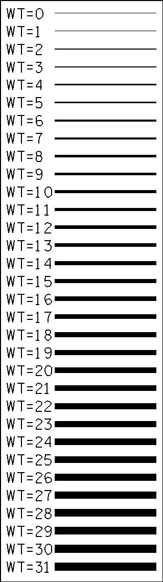
| 0 | 0.0060 | 0.10 | 1 | 0.0075 | 0.19 | 2 | 0.0090 | 0.23 | 3 | 0.0105 | 0.27 | 4 | 0.0120 | 0.30 | 5 | 0.0143 | 0.36 | 6 | 0.0176 | 0.45 | 7 | 0.0210 | 0.53 | 8 | 0.0243 | 0.62 | 9 | 0.0276 | 0.70 | 10 | 0.0310 | 0.79 | 11 | 0.0332 | 0.84 | 12 | 0.0354 | 0.90 | 13 | 0.0376 | 0.96 | 14 | 0.0398 | 1.01 | 15 | 0.0420 | 1.07 | 16 | 0.0442 | 1.12 | 17 | 0.0464 | 1.18 | 18 | 0.0486 | 1.23 | 19 | 0.0508 | 1.29 | 20 | 0.0530 | 1.35 | 21 | 0.0555 | 1.41 | 22 | 0.0580 | 1.47 | 23 | 0.0605 | 1.54 | 24 | 0.0630 | 1.60 | 25 | 0.0655 | 1.66 | 26 | 0.0680 | 1.73 | 27 | 0.0705 | 1.79 | 28 | 0.0730 | 1.85 | 29 | 0.0755 | 1.92 | 30 | 0.0780 | 1.98 | 31 | 0.0805 | 2.04 |
Standard MicroStation Libraries
| Type | Library File | Application |
|---|---|---|
| Color Table: | STDCOLOR.tbl | All projects |
| Standard Cell Libraries: | STDS.cel | English projects |
| METRIC.cel | Metric projects | |
| Sign Cell Libraries: | SIGN.cel | English projects |
| MSIGN.cel | Metric projects | |
| Font Resource: | TDOTFONT.rsc | All projects |
| Line Style Resource: | TDOTLINE.rsc | All projects |
| Level & Text StyleLibraries: | TDOTmain.dgnlib | All DGN files but cross sections |
| TDOTxsection.dgnlib | Cross section DGN files |
Standard Color Table - STDCOLOR.TBL
The following table lists the TDOT standard color table parameters. In order to provideconsistency with older drawings, this table shall be used with all Survey and Designdrawings.
| Number | Color | intensities | ||
|---|---|---|---|---|
| Red | Green | Blue | ||
| 0 | White | 255 | 255 | 255 |
| 1 | Gray | 135 | 135 | 135 |
| 2 | Manila | 255 | 205 | 150 |
| 3 | Light Blue | 0 | 205 | 255 |
| 4 | Dark Sky Blue | 60 | 60 | 255 |
| 5 | Orange | 255 | 135 | 0 |
| 6 | Red | 255 | 0 | 0 |
| 7 | Yellow | 255 | 255 | 0 |
| 8 | Green | 0 | 255 | 0 |
| 9 | Purple | 170 | 0 | 170 |
| 10 | Violet | 235 | 0 | 235 |
| 11 | Light Purple | 205 | 155 | 255 |
| 12 | Dark Tan | 135 | 85 | 85 |
| 13 | Light Brown | 205 | 130 | 100 |
| 14 | Olive | 170 | 255 | 160 |
| 15 | Dark Red | 190 | 0 | 90 |
| 16 | Pink | 250 | 0 | 150 |
| 17 | Dark Blue | 0 | 0 | 185 |
| 18 | Light Gray | 215 | 215 | 215 |
| 19 | Dark Purple | 110 | 45 | 130 |
| 20 | Light Green | 50 | 225 | 140 |
| 21 | Light Pink | 255 | 170 | 200 |
| 22 | Pale Blue | 0 | 255 | 255 |
| 23 | Pale Green | 180 | 255 | 185 |
| 24 | Yellow-Green | 150 | 255 | 0 |
| 25 | Copper | 255 | 165 | 50 |
| 26 | Rose | 255 | 85 | 85 |
| 27 | Blue-Violet | 150 | 0 | 255 |
| 28 | Dark Green | 0 | 175 | 0 |
| 29 | Light Violet | 145 | 85 | 115 |
| 30 | Apricot | 195 | 85 | 85 |
| 31 | Brown | 185 | 135 | 135 |
| 32 | Magenta | 235 | 135 | 150 |
| 50 | Black | 0 | 0 | 0 |
| 64 | Off White | 222 | 217 | 177 |
| 65 | Blue | 60 | 60 | 255 |
| 66 | Dark Brown | 135 | 85 | 85 |
| 67 | TDOT Logo Dark Green | 0 | 190 | 60 |
| 68 | TDOT Logo Light Green | 0 | 215 | 35 |
| 161 | Dark Gray | 85 | 85 | 85 |
| 253 | PDF Plot Border Purple | 147 | 112 | 219 |
| 254 | Plot Border Blue | 60 | 60 | 255 |
Standard Cell Area Patterning
Note that in some cases where dot patterns are used on large areas, MicroStation will issue a warning that a large number of graphics are about to be produced & asks if are you sure you wish to do this. If you are sure that your pattern scale is set correctly you can ignore this message and go on. If you are not sure, cancel and go check your scale.
Table Legend: AS = Active Scale F = Factor EF = English Factor MF = Metric Factor V = Value (#) = Small Dots Intensity
| Pattern Style | AP Cell | Pattern Scale | Pattern Angle | Pattern Delta (Row,Column) (V = F x AS) |
|---|---|---|---|---|
| Small Base Stone | bstone | AS x 0.5 | 0 | 0,0 |
| Earth | dearth | AS | 0 | 0,0 |
| Extra Large Dots | ddot | AS x 6 | 0 | V,V EF=.08 MF=.00200 |
| Drainage Easement | linee | AS | 60 | V,0 EF=.15 MF=.00375 |
| Loss of Access | linee | AS | 60 | V,0 EF=.15 MF=.00375 |
| Small Dumped Rock | dmprk | AS x 0.5 | 0 | 0,0 |
| Rip Rap | riprap | AS | 0 | 0,0 |
| Concrete | conc16 | AS | 0 | 0,0 |
| Reinforced Concrete | hatch | AS | 0 | 0,0 |
| Crown Vetch or Metal | metal | AS | 0 | V1,V2 EF=.05,.02 MF=.00125,.0005 |
| Scarify | zz | AS | 0 | 0,0 |
| Horizontal Lines | line | AS | 0 | V,0 EF=.20 MF=.005 |
| Vertical Lines | line | AS | 90 | V,0 EF=.20 MF=.005 |
| Dumped Rock | dmprk | AS | 0 | 0,0 |
| 45 Degree Lines | line | AS | 45 | V,0 EF=.20 MF=.005 |
| 135 Degree Lines | line | AS | 135 | V,0 EF=.20 MF=.005 |
| Base Stone | bstone | AS | 0 | 0,0 |
| Small Dots at 60 Deg. (1) | ddot | AS | 60 | V,V EF=.08 MF=.00200 |
| Small Dots at 90 Deg. (1) | ddot | AS | 90 | V,V EF=.07 MF=.00175 |
| Small Dots at 45 Deg. (1) | ddot | AS | 45 | V,V EF=.07 MF=.00175 |
| Small Dots at 90 Deg. (2) | ddot | AS | 90 | V,V EF=.06 MF=.00150 |
| Small Dots at 60 Deg. (2) | ddot | AS | 60 | V,V EF=.06 MF=.00150 |
| Small Dots at 90 Deg. (3) | ddot | AS | 90 | V,V EF=.05 MF=.00125 |
| Small Dots at 45 Deg. (3) | ddot | AS | 45 | V,V EF=.05 MF=.00125 |
| Small Dots at 90 Deg. (4) | ddot | AS x 2 | 90 | V,V EF=.04 MF=.00100 |
| Construction Easement (4) | ddot | AS x 2 | 45 | V,V EF=.04 MF=.00100 |
| Small Dots at 90 Deg. (5) | ddot | AS x 2 | 90 | V,V EF=.03 MF=.00075 |
| Slope Easement (5) | ddot | AS x 2 | 45 | V,V EF=.03 MF=.00075 |
| Small Dots at 90 Deg. (6) | ddot | AS x 2 | 90 | V,V EF=.02 MF=.00050 |
| Wetlands Mitigation Area (6) | ddot | AS x 2 | 45 | V,V EF=.02 MF=.00050 |
| Pvt. Drive Shading (6) | ddot | AS x 2 | 45 | V,V EF=.02 MF=.00050 |
| Traffic Control Work Zone | linewz | AS | 60 | V,0 EF=.20 MF=.005 |
| Erosion Control Dewatering Structure | dewatr | AS | 0 | 0,0 |
| Functional Bridge | funbr | AS | 0 | 0,0 |
| Functional Pavement | Funpvm | AS | 0 | 0,0 |
| Functional ROW | funrow | AS | 0 | 0,0 |
Standard Text Sizes
The following table provides CADD standard text sizes and weights for English-unit projects. Note that, for plot scales other than 1, text sizes can easily be extrapolated bymultiplying the text size (at AS=1) by the scale.
| Plot Text Size (inch) | Text Line Spacing 75% | Weight | Scale Text Size (feet) LS = 0.75 times text size | |||||
|---|---|---|---|---|---|---|---|---|
| AS=1 | AS=1 | 20 | 40 | 50 | 100 | 200 | 400 | |
| .100 | .075 | 2 | 2.0 | 4.0 | 5.0 | 10.0 | 20 | 40 |
| .120 | .090 | 2 | 2.4 | 4.8 | 6.0 | 12.0 | 24 | 48 |
| .140 | .105 | 4 | 2.8 | 5.6 | 7.0 | 14.0 | 28 | 56 |
| .175 | .131 | 7 | 3.5 | 7.0 | 8.75 | 17.5 | 35 | 70 |
| .200 | .150 | 10 | 4.0 | 8.0 | 10.0 | 20.0 | 40 | 80 |
| .240 | .180 | 10 | 4.8 | 9.6 | 12.0 | 24.0 | 48 | 96 |
| .290 | .218 | 13 | 5.8 | 11.6 | 14.5 | 29.0 | 58 | 116 |
| .350 | .263 | 13 | 7.0 | 14.0 | 17.5 | 35.0 | 70 | 140 |
| .425 | .319 | 14 | 8.5 | 17.0 | 21.3 | 42.5 | 85 | 170 |
| .500 | .375 | 17 | 10.0 | 20.0 | 25.0 | 50.0 | 100 | 200 |
| .700 | .525 | 20 | 14.0 | 28.0 | 35.0 | 70.0 | 140 | 280 |
The following table provides CADD standard text sizes and weights for metric projects.
| Plot Text Size (inch) AS=1 | Text Line Spacing 75% AS=1 | Weight | Scale Text Size (meters) LS = 0.75 times text size | |||
|---|---|---|---|---|---|---|
| 1 | 100 | 500 | 1000 | |||
| .100 | .075 | 2 | 0.0025 | 0.25 | 1.25 | 2.50 |
| .120 | .090 | 2 | 0.0030 | 0.30 | 1.50 | 3.00 |
| .140 | .105 | 4 | 0.0035 | 0.35 | 1.75 | 3.50 |
| .175 | .131 | 7 | 0.0045 | 0.45 | 2.25 | 4.50 |
| .200 | .150 | 10 | 0.0050 | 0.50 | 2.50 | 5.00 |
| .240 | .180 | 10 | 0.0060 | 0.60 | 3.00 | 6.00 |
| .290 | .218 | 13 | 0.0075 | 0.75 | 3.75 | 7.50 |
| .350 | .263 | 13 | 0.0090 | 0.90 | 4.50 | 9.00 |
| .425 | .319 | 14 | 0.0110 | 1.10 | 5.50 | 11.00 |
| .500 | .375 | 17 | 0.0125 | 1.25 | 6.25 | 12.50 |
| .700 | .525 | 20 | 0.0175 | 1.75 | 8.75 | 17.50 |
For all projects (English and metric), the line spacing (LS=__) should always be set to 75% of text size at any scale.
Standard Fonts - TDOTFONT.RSC
The standard text font is LEROYMON (#3). This is an equal-space font, designed toapproximate the appearance of Leroy lettering used on plans in the past. Font #3 should always be used for TDOT work, unless there is a good reason to use another one.LEROYPRO (#2) is a proportional-space version of Font #3. It may used when available space for text is small and it is desirable not to reduce the text size. LEROYSTD (#5) is a modified version of Font #3, which is used for Standard Drawings only and is not applicable to plans development.
Font1 (#1) is a proportional-space font, with tighter packing than Font #2. It not as close a match to Leroy lettering as Fonts #2 or #3. Font000 (#0) is an equal-space version ofFont #1. . These are supplied with MicroStation but are not a close match to Leroy lettering, so CADD operators should not use them in Design Division plans.
ALIGNMENT (#94) is a symbol font used by the Design Division for horizontal and vertical alignment points. TERRAMODEL (#6), PLUS3SYM (#9), CONTINENTAL( #90) and Features (#93) are old symbol fonts used in the past by the Design Division and are kept to support old project data. They should not be used for any new data.
USERNOTE (#64) is a special "red-lining" font, which will not plot when the standard Iplot pen tables are used. It should be used when it is desirable to make notes in a project file which should not appear on the project prints.
Windows based true type font Arial is used with Office files which are linked to MicroStation design files. Blue Highway Condensed (#195) was used in the past withOffice and is still provided to support old project data.
Font007 (#7), BSK401B (#11), font012 (#12), MONOS810 (#13), font023 (#23), font041 (#41) and font042 (#42) are MicroStation-supplied fonts, and should not beused often; most of them take considerable processor time to plot. They are useful forheadings, etc. Unlike every other text font listed here, characters in Font #7 are not thesame height (for a given text size) as they would be in another font. Font #11 mimics the appearance of printed material. Font #12 is an italic version of Font #11. Font #13 mimics the appearance of typed material. Font #23 is an italic version of font #1. It is difficult to read at small text sizes. Font #41 mimics a style of hand-lettering popular in some drafting environments. Font #42 is a non-filled block letter style.
All fonts specifically used by the Design Division are described above. Several other fonts are found in the font resource file. These include the standard fonts used by the Mapping Division and the Structures Division. A combined font resource file is used to provide for the sharing of files between divisions.
Standard Characters & Symbols
The following table shows which characters or symbols are available in a given font, along with the octal code for that symbol. A check mark in a column for a font indicates that the symbol described at left is available in that font. A character or symbol other than a check mark indicates that the octal code is used for the symbol shown for that font, rather than the standard symbol. A blank indicates that the symbol is not available and that the octal code is undefined in that particular font (in a design file, an undefined character will appear as a blank).
DECOCT char name font0 1 2 3 5 7 11 12 13 23 41 42
| 008 | 010 | ^H | backspace | √ | √ | √ | √ | √ | √ | √ | √ | √ | √ | √ | |
| 009 | 011 | ^I | horizontal tab | √ | √ | √ | √ | √ | √ | √ | √ | √ | √ | √ | |
| 032 | 040 | space | √ | √ | √ | √ | √ | √ | √ | √ | √ | √ | √ | √ | |
| 033 | 041 | ! | exclamation point | √ | √ | √ | √ | √ | √ | √ | √ | √ | √ | √ | √ |
| 043 | 042 | “ | double quote | √ | √ | √ | √ | √ | √ | √ | √ | √ | √ | √ | |
| 035 | 043 | # | number sign | √ | √ | √ | √ | √ | √ | √ | √ | √ | √ | √ | |
| 036 | 044 | $ | dollar sign | √ | √ | √ | √ | φ1 | √ | √ | √ | √ | √ | √ | √ |
| 037 045 % | per cent sign | √ | √ | √ | √ | √ | √ | √ | √ | √ | √ | ||
|---|---|---|---|---|---|---|---|---|---|---|---|---|---|
| 038 046 & | ampersand | √ | √ | √ | √ | √ | √ | √ | √ | √ | √ | √ | √ |
| 039 047 ‘ | apostrophe | √ | √ | √ | √ | √ | √ | √ | √ | √ | √ | ||
| 040 050 ( | open parenthesis | √ | √ | √ | √ | √ | √ | √ | √ | √ | √ | √ | |
| 041 051 ) | close parenthesis | √ | √ | √ | √ | √ | √ | √ | √ | √ | √ | √ | |
| 042 052 * | asterisk | √ | √ | √ | √ | √ | √ | √ | √ | √ | √ | ||
| 043 053 + | plus | √ | √ | √ | √ | √ | √ | √ | √ | √ | √ | ||
| 044 054 , | comma | √ | √ | √ | √ | √ | √ | √ | √ | √ | √ | √ | √ |
| 045 055 - | hyphen | √ | √ | √ | √ | √ | √ | √ | √ | √ | √ | √ | √ |
| 046 056 . | period | √ | √ | √ | √ | √ | √ | √ | √ | √ | √ | √ | √ |
| 047 057 / | slash | √ | √ | √ | √ | √ | √ | √ | √ | √ | √ | ||
| 048 060 0 | zero | √ | √ | √ | √ | √ | √ | √ | √ | √ | √ | ||
| 049 061 1 | one | √ | √ | √ | √ | √ | √ | √ | √ | √ | √ | √ | √ |
| 050 062 2 | two | √ | √ | √ | √ | √ | √ | √ | √ | √ | √ | √ | √ |
| 051 063 3 | three | √ | √ | √ | √ | √ | √ | √ | √ | √ | √ | √ | √ |
| 052 064 4 | four | √ | √ | √ | √ | √ | √ | √ | √ | √ | √ | √ | √ |
| 053 065 5 | five | √ | √ | √ | √ | √ | √ | √ | √ | √ | √ | √ | √ |
| 054 066 6 | six | √ | √ | √ | √ | √ | √ | √ | √ | √ | √ | √ | √ |
| 055 067 7 | seven | √ | √ | √ | √ | √ | √ | √ | √ | √ | √ | √ | √ |
| 056 070 8 | eight | √ | √ | √ | √ | √ | √ | √ | √ | √ | √ | √ | √ |
| 057 071 9 | nine | √ | √ | √ | √ | √ | √ | √ | √ | √ | √ | √ | √ |
| 058 072 : | colon | √ | √ | √ | √ | √ | √ | √ | √ | √ | √ | √ | √ |
| 059 073 ; | semicolon | √ | √ | √ | √ | √ | √ | √ | √ | √ | √ | √ | √ |
| 060 074 < | less than | √ | √ | √ | √ | √ | √ | √ | √ | √ | √ | ||
| 061 075 = | equal | √ | √ | √ | √ | √ | √ | √ | √ | √ | √ | √ | |
| 062 076 > | greater than | √ | √ | √ | √ | √ | √ | √ | √ | √ | √ | ||
| 063 077 ? | question mark | √ | √ | √ | √ | √ | √ | √ | √ | √ | √ | √ | √ |
| 064 100 @ | commercial at | √ | √ | √ | √ | √ | √ | √ | √ | √ | √ | ||
| 065 101 A | upper-case A | √ | √ | √ | √ | √ | √ | √ | √ | √ | √ | √ | |
| 066 102 B | upper-case B | √ | √ | √ | √ | √ | √ | √ | √ | √ | √ | √ | |
| 067 103 C | upper-case C | √ | √ | √ | √ | √ | √ | √ | √ | √ | √ | √ | |
| 068 104 D | upper-case D | √ | √ | √ | √ | √ | √ | √ | √ | √ | √ | √ | |
| 069 105 E | upper-case E | √ | √ | √ | √ | √ | √ | √ | √ | √ | √ | √ | |
| 070 106 F | upper-case F | √ | √ | √ | √ | √ | √ | √ | √ | √ | √ | √ | |
| 071 107 G | upper-case G | √ | √ | √ | √ | √ | √ | √ | √ | √ | √ | √ | |
| 072 110 H | upper-case H | √ | √ | √ | √ | √ | √ | √ | √ | √ | √ | √ | |
| 1 diameter symbol | |||||||||||||
| 28 | |||||||||||||
2
| DEC | OCT | char | name font 0 1 2 3 5 7 11 12 13 23 41 42 |
| 073 | 111 | I | upper-case I |
| 074 | 112 | J | upper-case J √ √ √ √ √ √ √ √ √ √ √ √ √ √ √ √ √ √ √ ±√ √ √ √ √ √ √ √ √ √ √ √ √ √ √ √ √ √ √ ± √ ° √ √ √ √ √ √ √ √ √ √ √ √ √ √ √ √ √ √ √ ± √ ° √ √ √ √ √ √ √ √ √ √ √ √ √ √ √ √ √ √ √ √ √ √ √ √ √ √ √ √ √ √ √ √ √ √ √ √ |
| 075 | 113 | K | upper-case K |
| 076 | 114 | L | upper-case L |
| 077 | 115 | M | upper-case M |
| 078 | 116 | N | upper-case N |
| 079 | 117 | O | upper-case O |
| 080 | 120 | P | upper-case P |
| 081 | 121 | Q | upper-case Q |
| 082 | 122 | R | upper-case R |
| 083 | 123 | S | upper-case S |
| 084 | 124 | T | upper-case T |
| 085 | 125 | U | upper-case U |
| 086 | 126 | V | upper-case V |
| 087 | 127 | W | upper-case W |
| 088 | 130 | X | upper-case X |
| 089 | 131 | Y | upper-case Y |
| 090 | 132 | Z | upper-case Z |
| 091 | 133 | [ | open bracket |
grave accent lower-case a lower-case b lower-case c lower-case d lower-case e lower-case f lower-case g lower-case h lower-case i lower-case j lower-case k lower-case l lower-case m lower-case n lower-case o lower-case p lower-case q lower-case r lower-case s lower-case t lower-case u lower-case v lower-case w lower-case x lower-case y lower-case z
√√√√√√√√√√√√√√√√√√√√√√√√√√√√√√√√√√√√√√√√√√√√√√√√√√√
√√√√√√√√√√√√√√√√√√√√√√√√√√√√√√√√√√√√√√√√√√√√√√√√√√√
√√√√√√√√√√√√√√√√√√√√√√√√√√√√√√√√√√√√√√√√√√√√√√√√√√√ √√√√√√√√√√√√√√√√√√√√√√√√√√√√√√√√√√√√√√√√√√√√√√√√√√√ √√√√√√√√√√√√√√√√√√√√√√√√√√√√√√√√√√√√√√√√√√√√√√√√√√√ √√√√√√√√√√√√√√√√√√√√√√√√√√√√√√√√√√√√√√√√√√√√√√√√√√√
√√√√√√√√√√√√√√√√√√√√√√√√√√
√°√Θ
√√√√√√√√√√√√√√√√√√√√√√√√√√√ √Θ√√√√√√√√√√√√√√√√√√√√√√√√√√ √Θ√√√√√√√√√√√√√√√√√√√√√√√√√√
√√√√√√√√√√√√√√√√√√√√√√√√√√√
cl 5 cl
| 092 | 134 | \ | backslash |
| 093 | 135 | ] | close bracket |
| 094 | 136 | ^ | circumflex |
| 095 | 137 | _ | underline |
| 096 | 140 | ` |
|---|---|---|
| 097 | 141 | a |
| 098 | 142 | b |
| 099 | 143 | c |
| 100 | 144 | d |
| 101 | 145 | e |
| 102 | 146 | f |
| 103 | 147 | g |
| 104 | 150 | h |
| 105 | 151 | i |
| 106 | 152 | j |
| 107 | 153 | k |
| 108 | 154 | l |
| 109 | 155 | m |
| 110 | 156 | n |
| 111 | 157 | o |
| 112 | 160 | p |
| 113 | 161 | q |
| 114 | 162 | r |
| 115 | 163 | s |
| 116 | 164 | t |
| 117 | 165 | u |
| 118 | 166 | v |
| 119 | 167 | w |
| 120 | 170 | x |
| 121 | 171 | y |
| 122 | 172 | z |
123 173 { open brace
2 plus-or-minus symbol
3 degree symbol
4 theta
| DEC | OCT | char | name | font | 0 | 1 | 2 | 3 | 5 | 7 | 11 | 12 | 13 | 23 | 41 | 42 |
| 124 125 | 174 175 | | } | vertical line close brace | √ √ | √ √ | cl √ | √ pl6 | √ bl7 | √ √ | √ √ | √ √ | √ √ | ||||
| 126 | 176 | ~ | tilde | √ | √ | Δ8 | Δ | Δ | √ | √ | √ | √ | ||||
| 129 | 201 | fraction 1/2 | √ | √ | √ | √ | √ | √ | ||||||||
| 130 | 202 | fraction 1/4 | √ | √ | √ | √ | √ | √ | ||||||||
| 131 | 203 | fraction 3/4 | √ | √ | √ | √ | √ | √ | ||||||||
| 132 | 204 | fraction 1/8 | √ | √ | √ | √ | √ | √ | ||||||||
| 133 | 205 | fraction 3/8 | √ | √ | √ | √ | √ | √ | ||||||||
| 134 | 206 | fraction 5/8 | √ | √ | √ | √ | √ | √ | ||||||||
| 135 | 207 | fraction 7/8 | √ | √ | √ | √ | √ | √ | ||||||||
| 136 | 210 | fraction 1/16 | √ | √ | √ | √ | √ | √ | ||||||||
| 137 | 211 | fraction 3/16 | √ | √ | √ | √ | √ | √ | ||||||||
| 138 | 212 | fraction 5/16 | √ | √ | √ | √ | √ | √ | ||||||||
| 139 | 213 | fraction 7/16 | √ | √ | √ | √ | √ | √ | ||||||||
| 140 | 214 | fraction 9/16 | √ | √ | √ | √ | √ | √ | ||||||||
| 141 | 215 | fraction 11/16 | √ | √ | √ | √ | √ | √ | ||||||||
| 142 | 216 | fraction 13/16 | √ | √ | √ | √ | √ | √ | ||||||||
| 143 | 217 | fraction 15/16 | √ | √ | √ | √ | √ | √ | ||||||||
| 144 | 220 | fraction 1/32 | √ | √ | √ | √ | √ | √ | ||||||||
| 145 | 221 | fraction 3/32 | √ | √ | √ | √ | √ | √ | ||||||||
| 146 | 222 | fraction 5/32 | √ | √ | √ | √ | √ | √ | ||||||||
| 147 | 223 | fraction 7/32 | √ | √ | √ | √ | √ | √ | ||||||||
| 148 | 224 | fraction 9/32 | √ | √ | √ | √ | √ | √ | ||||||||
| 149 | 225 | fraction 11/32 | √ | √ | √ | √ | √ | √ | ||||||||
| 150 | 226 | fraction 13/32 | √ | √ | √ | √ | √ | √ | ||||||||
| 151 | 227 | fraction 15/32 | √ | √ | √ | √ | √ | √ | ||||||||
| 152 | 230 | fraction 17/32 | √ | √ | √ | √ | √ | √ | ||||||||
| 153 | 231 | fraction 19/32 | √ | √ | √ | √ | √ | √ | ||||||||
| 154 | 232 | fraction 21/32 | √ | √ | √ | √ | √ | √ | ||||||||
| 155 | 233 | fraction 23/32 | √ | √ | √ | √ | √ | √ | ||||||||
| 156 | 234 | fraction 25/32 | √ | √ | √ | √ | √ | √ | ||||||||
| 157 | 235 | fraction 27/32 | √ | √ | √ | √ | √ | √ | ||||||||
| 158 | 236 | fraction 29/32 | √ | √ | √ | √ | √ | √ | ||||||||
| 159 | 237 | fraction 31/32 | √ | √ | √ | √ | √ | √ | ||||||||
| 160 | 240 | fraction 1/64 | √ | √ | √ | √ | √ | √ | ||||||||
| 161 | 241 | fraction 3/64 | √ | √ | √ | √ | √ | √ | ||||||||
| 162 | 242 | fraction 5/64 | √ | √ | √ | √ | √ | √ | ||||||||
| 163 | 243 | fraction 7/64 | √ | √ | √ | √ | √ | √ | ||||||||
| 164 | 244 | fraction 9/64 | √ | √ | √ | √ | √ | √ | ||||||||
| 165 | 245 | fraction 11/64 | √ | √ | √ | √ | √ | √ | ||||||||
| 166 | 246 | fraction 13/64 | √ | √ | √ | √ | √ | √ | ||||||||
| 167 | 247 | fraction 15/64 | √ | √ | √ | √ | √ | √ | ||||||||
| 168 | 250 | fraction 17/64 | √ | √ | √ | √ | √ | √ | ||||||||
| 169 | 251 | fraction 19/64 | √ | √ | √ | √ | √ | √ | ||||||||
| 170 | 252 | fraction 21/64 | √ | √ | √ | √ | √ | √ | ||||||||
| 171 | 253 | fraction 23/64 | √ | √ | √ | √ | √ | √ | ||||||||
| 172 | 254 | fraction 25/64 | √ | √ | √ | √ | √ | √ | ||||||||
| 173 | 255 | fraction 27/64 | √ | √ | √ | √ | √ | √ | ||||||||
| 174 | 256 | fraction 29/64 | √ | √ | √ | √ | √ | √ | ||||||||
| 175 | 257 | fraction 31/64 | √ | √ | √ | √ | √ | √ |
5 centerline symbol 6 property line symbol 7 baseline symbol 8 delta
30 9 superscript 2 (squared) 10 superscript 3 (cubed) 11 diameter symbol 12 mu (micro symbol) 13 baseline symbol
| DEC | OCT | char | name | font | 0 | 1 | 2 | 3 | 5 | 7 | 11 | 12 | 13 | 23 | 41 | 42 |
| 176 | 260 | fraction 33/64 | √ | √ | √ | √ | √ | √ | ||||||||
| 177 | 261 | fraction 35/64 | √ | √ | √ | √ | √ | √ | ||||||||
| 178 | 262 | fraction 37/64 | √ | √ | √ | √ | √ | √ | ||||||||
| 179 | 263 | fraction 39/64 | √ | √ | √ | √ | √ | √ | ||||||||
| 180 | 264 | fraction 41/64 | √ | √ | √ | √ | √ | √ | ||||||||
| 181 | 265 | fraction 43/64 | √ | √ | √ | √ | √ | √ | ||||||||
| 182 | 266 | fraction 45/64 | √ | √ | √ | √ | √ | √ | ||||||||
| 183 | 267 | fraction 47/64 | √ | √ | √ | √ | √ | √ | ||||||||
| 184 | 270 | fraction 49/64 | √ | √ | √ | √ | √ | √ | ||||||||
| 185 | 271 | fraction 51/64 | √ | √ | √ | √ | √ | √ | ||||||||
| 186 187 188 189 | 272 273 274 275 | fraction 53/64 fraction 55/64 fraction 57/64 fraction 59/64 | √ √ √ √ | √ √ √ √ | √ √ √ √ | √ 29 310 φ11 | √ √ √ √ | √ √ √ √ | ||||||||
| 190 191 | 276 277 | fraction 61/64 fraction 63/64 | √ √ | √ √ | √ √ | μ12 bl13 | √ √ | √ √ | ||||||||
| 200 | 310 | ± | plus/minus | √ | √ |
31
Standard Special Symbols
| LEROYMON (Font #3) | |||
| For: | Enter: | Description | |
| centerline symbol | { or | \123 | left brace |
| property line symbol | } or | \125 | right brace |
| baseline symbol | 63/64 or | \191 | 63/64 |
| delta (Δ) | ~ or | \126 | tilde |
| theta (Θ) | ` or | \96 | left single quote (accent) |
| degree (°) | ^ or | \94 | caret |
| plus-or-minus (±) | \ or | \92 | backslash |
| diameter (∅) | 59/64 or | \189 | 59/64 |
| micro (μ) | 61/64 or | \190 | 61/64 |
| squared (superscript 2; 2) | 55/64 or | \187 | 55/64 |
| cubed (superscript 3; 3) | 57/64 or | \188 | 57/64 |
| LEROYSTD (Font #5) | ||||
| Font #5 is to be used only on Stand | ard Drawings. | |||
| For: | Enter: | Description | ||
| centerline symbol | { | or | \123 | left brace |
| baseline symbol | } | or | \125 | right brace |
| delta (Δ) | ~ | or | \126 | tilde |
| theta (Θ) | ` | or | \96 | left single quote (accent) |
| degree (°) | ^ | or | \94 | caret |
| plus-or-minus (±) | \ | or | \92 | backslash |
| diameter (∅) | $ | or | \36 | dollar |
Standard Text Styles – TDOTmain.dgnlib & TDOTxsection.dgnlib
These dgnlib files contain standard text styles which can be used for placing general labels or notes not automatically placed by special functions or other programs. DGN seed files have the same text styles loaded by default as well. Text styles accessed through MicroStation’s text tools set the basic text parameters based on a scale of 50 and the desired color. To use these to their best advantage they should be accessed through the special VBA programs Text Styles Plus and XS Text Styles Plus. These programs not only set the appropriate text style but also the level and weight required. The text sizes are automatically updated based on the current active scale and the current active color is set to match the text style color in case leader lines are required. They can be accessed via the TDOT drop down menu or from Geopak’s D&C Manager.
Main Text Style List
Aerial Survey - Photo Control
Building - Exist.
Business - Functional
Centerline - Exist. Road
Centerline - Prelim.
Centerline - Prop.
Centerline Curve - Exist. Road
Centerline Curve - Prelim.
Centerline Curve - Prop.
Drainage - Natural
Drainage - Prop.
Drainage Area Shape - Exist.
Drainage Br. & Cross Drain Size Prop.
Drainage Br. Deck - Exist.
Drainage Br. Hydraulic Data - Exist.
Drainage Bridge - Exist.
Drainage Pipe & Culvert - Exist.
Drainage Storm Sewer - Exist.
Easement - Exist.
Erosion Control
Guardrail - Exist.
Guardrail - Prop.
Lighting - Prop.
Non-Transportation - Exist.
Pavement Marking - Exist.
Pavement Marking - Prop.
Political Boundary
Profile - Prop.
Profile Curve - Prop.
Profile Drainage - Natural
Profile Drainage - Prop.
Profile Drainage Bridge - Exist.
Profile Drainage Pipe & Culvert - Exist.
Profile Drainage Storm Sewer - Exist.
Profile Drainage Storm Sewer - Prop.
Profile Existing Road
Profile Ground Line
Profile Project Info - Exist.
Profile Project Info Name - Exist.
Profile Survey Control
Profile Utilities Cable – Exist.
Profile Utilities Electric - Exist.
Profile Utilities Gas - Exist.
Profile Utilities OH - Exist.
Profile Utilities Sanitary Sewer - Exist.
Profile Utilities Telephone - Exist.
Profile Utilities Water - Exist.
Project Info - Exist.
Property Line - Exist.
Property Marker - Exist.
Property Owner
Property Tract/Parcel Number
Railroad - Exist.
Roads - Exist
Roads - Functional
Roads - Prop.
Roadside Barriers - Exist.
Roadside Barriers - Prop.
ROW & Easements - Prop.
ROW - Exist.
ROW - Functional
ROW Bearing & Distance - Prop.
ROW Marker - Exist.
ROW Sta. & Offset - Exist.
ROW Sta. & Offset - Prop.
Scarification - Prop.
Scratch
Signalization - Prop.
Signs - Exist.
Signs - Prop.
Signs - Temporary
Slope Line - Prop.
Survey Control
Survey Control - Temporary
Traffic Control - Exist.
Traffic Control - Prop.
Traffic Control - Temporary
Transportation - Exist.
Transportation - Prop.
Transportation Urban - Exist.
Transportation Urban - Prop.
Utilities Cable UG - Exist.
Utilities Cable OH - Prop.
Utilities Cable UG - Prop.
Utilities Electric & Cable OH - Prop.
Utilities Electric OH - Exist.
Utilities Electric OH - Prop.
Utilities Electric Tele. & Cable OH - Prop.
Utilities Electric UG - Exist.
Utilities Electric UG - Prop.
Utilities Fiber Optic UG - Exist.
Utilities Fiber Optic OH - Prop.
Utilities Fiber Optic UG - Prop.
Utilities Gas - Exist.
Utilities Gas - Prop.
Utilities Lighting - Exist.
Utilities Lighting - Prop.
Utilities Owners - Exist.
Utilities Poles - Exist.
Utilities Sanitary Sewer - Exist.
Utilities Sanitary Sewer - Prop.
Utilities Telephone OH - Exist.
Utilities Telephone OH - Prop.
Utilities Telephone UG - Exist.
Utilities Telephone UG - Prop.
Utilities Water - Exist.
Utilities Water - Prop.
Vegetation - Exist.
Vegetation - Prop.
| Cross Section Text Style List | ||
|---|---|---|
| Bridge Limits - Prop. | Finished Grade Slopes - Prop. | ROW - Prop. |
| Drainage - Exist. | Pavement - Exist. | Scratch |
| Drainage - Prop. | Retaining Wall - Prop. | Subgrade Slopes - Prop. |
| Finished Grade - Prop. | ROW - Exist. | Superelevation Limits - Prop. |
Standard Line Styles - TDOTLINE.RSC
This file contains custom line styles used by the Design Division. The file was created in 2D so line styles can be used in 2D or 3D design files. All line styles are created at a scale of 1. Custom line styles are used automatically by Geopak’s D&C manager DDB database and SMD feature table.
To use a line style at a particular scale make the appropriate settings as follows:
- 1.
- Go to the Attributes tool box and under line style selection choose the line style byname, go to the drop down menu option Element>Line Styles>Custom or keyin LINESTYLE SETTINGS and choose the line style from the Line Styles dialog bydouble clicking on it.
- 2.
- To set the scale, in the Line Styles dialog click on the Scale Factor button if not already on and set the scale factor to the scale value desired.
- 3.
- Use whatever element placement tool needed and appearance will be as desired.
NOTE: All line styles were built in an English design file. To use for metric projects multiply desired scale by .025. Example: For 500 scale...... 500 X .025 = 12.5
To change the scale of element(s) using a custom linestyle:
- 1.
- Fence the elements, group together with a selection set or identify one at a time once the settings are made.
- 2.
- Repeat steps 1-2 as listed above to set scale and style desired.
- 3.
- Then use the Change Element Attributes tool to change the line style of theelement(s).
or...
Fence the elements, group together with a selection set or identify a single element
after keyin.
4. Keyin CHANGE LINESTYLE SCALE (new scale)
To change the location of text or symbols on an element using a custom linestyle to improve readability or appearance:
- 1.
- On the Change Attributes tool box get the Modify Linestyle command. Set the tool settings bar to Shift.
- 2.
- Identify element with a data point and then move cursor left or right to shift symbols.
- 3.
- Data point to accept new location.
NOTE: You can also access this through the keyin... MODIFY LINESTYLE SHIFT or from the TDOT drop down menu bar under Custom Line Styles.
Example: This is a great way to fix short property lines on which a PL symbol did not show up.
To flip or reverse the display of a custom linestyle
- 1.
- On the B Spline Modify Curves tool box get the Change Element Directioncommand.
- 2.
- Identify the beginning of element with a data point and then data point near the other end to indicate the new beginning location.
NOTE: You can also access this through the keyin... CHANGE DIRECTION or from the TDOT drop down menu bar under Custom Line Styles
Custom Line Style Name List
0 BLANK 1"GAS LINE 1"GAS LINE PROP 1"SUE GAS LINE 1"SUE WATER LINE 1"WATER LINE 1"WATER LINE PROP 1-1/2"GAS LINE 1-1/2"GAS LINE PROP 1-1/2"WATER LINE 1-1/2"WATER LINE PROP 1-1/4"GAS LINE 1-1/4"GAS LINE PROP 1-1/4"SUE GAS LINE 1-1/4"SUE WATER LINE 1-1/4"WATER LINE 1-1/4"WATER LINE PROP 1/2"GAS LINE 1/2"GAS LINE PROP 1/2"SUE GAS LINE 1/2"SUE WATER LINE 1/2"WATER LINE 1/2"WATER LINE PROP 10"FMS LINE 10"FMS LINE PROP 10"GAS LINE 10"GAS LINE PROP 10"SA LINE 10"SA LINE PROP 10"ST LINE 10"SUE GAS LINE 10"SUE SA LINE 10"SUE WATER LINE 10"WATER LINE 10"WATER LINE PROP 12"FMS LINE 12"FMS LINE PROP 12"GAS LINE 12"GAS LINE PROP 12"SA LINE 12"SA LINE PROP 12"ST LINE 12"SUE GAS LINE 12"SUE SA LINE 12"SUE WATER LINE 12"WATER LINE 12"WATER LINE PROP 14"FMS LINE 14"FMS LINE PROP 14"GAS LINE 14"GAS LINE PROP 14"SA LINE 14"SA LINE PROP 14"ST LINE 14"SUE GAS LINE 14"SUE SA LINE 14"SUE WATER LINE 14"WATER LINE 14"WATER LINE PROP 15"GAS LINE 15"GAS LINE PROP 15"SA LINE 15"SA LINE PROP 15"ST LINE 15"SUE GAS LINE 15"SUE SA LINE 15"SUE WATER LINE 15"WATER LINE 15"WATER LINE PROP 16"FMS LINE 16"FMS LINE PROP 16"GAS LINE 16"GAS LINE PROP 16"SA LINE 16"SA LINE PROP 16"ST LINE 16"SUE GAS LINE 16"SUE SA LINE 16"SUE WATER LINE 16"WATER LINE 16"WATER LINE PROP 18"FMS LINE 18"FMS LINE PROP 18"SA LINE 18"SA LINE PROP 18"ST LINE 18"SUE GAS LINE 18"SUE SA LINE 18"SUE WATER LINE 18"WATER LINE 18"WATER LINE PROP 2"FMS LINE 2"FMS LINE PROP 2"GAS LINE 2"GAS LINE PROP 2"SUE GAS LINE 2"SUE WATER LINE 2"WATER LINE 2"WATER LINE PROP 20"FMS LINE 20"FMS LINE PROP 20"SA LINE 20"SA LINE PROP 20"ST LINE 20"SUE GAS LINE 20"SUE SA LINE 20"SUE WATER LINE 20"WATER LINE 20"WATER LINE PROP 22"FMS LINE 22"FMS LINE PROP 22"SA LINE 22"SA LINE PROP 22"ST LINE 22"SUE GAS LINE 22"SUE SA LINE 22"SUE WATER LINE 22"WATER LINE 22"WATER LINE PROP 24"FMS LINE 24"FMS LINE PROP 24"GAS LINE 24"GAS LINE PROP 24"SA LINE 24"SA LINE PROP 24"ST LINE 24"SUE GAS LINE 24"SUE SA LINE 24"SUE WATER LINE 24"WATER LINE 24"WATER LINE PROP 26"FMS LINE 26"FMS LINE PROP 26"GAS LINE 26"GAS LINE PROP 26"SA LINE 26"SA LINE PROP 26"WATER LINE 26"WATER LINE PROP 27"SA LINE 27"SA LINE PROP 27"ST LINE 27"SUE GAS LINE 27"SUE SA LINE 27"SUE WATER LINE 27"WATER LINE 27"WATER LINE PROP 28"FMS LINE 28"FMS LINE PROP 28"SA LINE 28"SA LINE PROP 3"GAS LINE 3"GAS LINE PROP 3"SUE GAS LINE 3"SUE WATER LINE 3"WATER LINE 3"WATER LINE PROP 3/4"GAS LINE 3/4"GAS LINE PROP 3/4"SUE GAS LINE 3/4"SUE WATER LINE 3/4"WATER LINE 3/4"WATER LINE PROP 30"FMS LINE 30"FMS LINE PROP 30"GAS LINE 30"GAS LINE PROP 30"SA LINE 30"SA LINE PROP 30"ST LINE 30"SUE GAS LINE 30"SUE SA LINE 30"SUE WATER LINE 30"WATER LINE 30"WATER LINE PROP 32"SA LINE 32"SA LINE PROP 32"ST LINE 32"SUE GAS LINE 32"SUE SA LINE 32"SUE WATER LINE 32"WATER LINE 32"WATER LINE PROP 34"SA LINE 34"SA LINE PROP 34"ST LINE 34"SUE GAS LINE 34"SUE SA LINE 34"SUE WATER LINE 34"WATER LINE 34"WATER LINE PROP 36"GAS LINE 36"GAS LINE PROP 36"SA LINE 36"SA LINE PROP 36"ST LINE 36"SUE GAS LINE 36"SUE SA LINE 36"SUE WATER LINE 36"WATER LINE 36"WATER LINE PROP 4"FMS LINE 4"FMS LINE PROP 4"GAS LINE 4"GAS LINE PROP 4"SA LINE 4"SA LINE PROP 4"SUE GAS LINE 4"SUE WATER LINE 4"WATER LINE 4"WATER LINE PROP 40"SA LINE 40"SA LINE PROP 40"ST LINE 40"SUE GAS LINE 40"SUE SA LINE 40"SUE WATER LINE 40"WATER LINE 40"WATER LINE PROP 42"SA LINE 42"SA LINE PROP 42"ST LINE 42"SUE GAS LINE 42"SUE SA LINE 42"SUE WATER LINE 42"WATER LINE 42"WATER LINE PROP 45"SA LINE 45"SA LINE PROP 45"ST LINE 45"SUE SA LINE 45"SUE WATER LINE 48"SA LINE 48"SA LINE PROP 48"ST LINE 48"SUE SA LINE 48"SUE WATER LINE 5/8"GAS LINE 5/8"GAS LINE PROP 54"SA LINE 54"SA LINE PROP 54"ST LINE 54"SUE SA LINE 6"FMS LINE 6"FMS LINE PROP 6"GAS LINE 6"GAS LINE PROP 6"SA LINE 6"SA LINE PROP 6"SUE GAS LINE 6"SUE SA LINE 6"SUE WATER LINE 6"WATER LINE 6"WATER LINE PROP 60"SA LINE 60"SA LINE PROP 60"ST LINE 60"SUE SA LINE 66"SA LINE 66"SA LINE PROP 66"ST LINE 66"SUE SA LINE 72"SA LINE 72"SA LINE PROP 72"ST LINE 72"SUE SA LINE 8"FMS LINE 8"FMS LINE PROP 8"GAS LINE 8"GAS LINE PROP 8"SA LINE 8"SA LINE PROP 8"SUE GAS LINE 8"SUE SA LINE 8"SUE WATER LINE 8"WATER LINE 8"WATER LINE PROP BARRICADE BARRIER WALL PORT BERM BRIDGE DRAIN 18" PROP C&G 4-30 M C&G 4-36 M C&G 4-42 M C&G 6-30 C&G 6-33 M C&G 6-36 C&G 6-39 M C&G 6-42 C&G 6-45 M CABLE CABLE (UG) CABLE (UG) PROP CABLE PROP CENTER LINE CITY LINE CLTEMP CONTINUOUS COUNTY LINE CROSSWALK CROSSWALK LONGITUDINAL CURB Curb 4" M Type A Curb 4" M Type B Curb 6" M Type A Curb 6" M Type B Curb 6" Type A Curb 6" Type B DASH DASH3 DIMENSION LINE DITCH SPEC DITCH SPEC SHORT DIV CHAN TEMP DOTS FENCE FIBER (UG) FIBER (UG) PROP FIBER OPTIC FIBER OPTIC PROP FILTER BARRIER FMS LINE FMS LINE PROP FOREST LINE GAS LINE GAS LINE PROP GR Br End Prop GR Br Rail Prop GR Term Inline GR Term Type 12 GR Term Type 13 GR Term Type 21 GR Term Type 38 GRID LINE GUARDRAIL LT GUARDRAIL MED GUARDRAIL MED PROP GUARDRAIL RT GUARDRAIL SIN PROP GUY GUY PROP HATCH IN (CW) HATCH OUT (CW) HAY BALES HEDGE LEADER LARGE LEADER LINE LEADER SMALL LONG DASH DOT LONG SHORT DASH LONG TWO SHORT MB GLARE WALL MB GLARE WALL-PIER MB WALL MB WALL-GR MB WALL-PIER MEDIAN SLOPE OH WIRE XING P/C P/C PROP P/T P/T PROP P/T/C P/T/C PROP PAP LOC CL PIPE CULVERT 18" PROP PIPE CULVERT 24" PROP PIPE CULVERT 30" PROP PIPE CULVERT 36" PROP PIPE CULVERT 42" PROP PIPE CULVERT 48" PROP PIPE CULVERT 54" PROP PIPE CULVERT 60" PROP PIPE CULVERT 66" PROP PIPE CULVERT 72" PROP PIPE CULVERT 78" PROP PIPE CULVERT 84" PROP POWER POWER (UG) POWER (UG) PROP POWER PROP POWER/CABLE POWER/CABLE PROP PROPERTY PVMT MRK 10-30 W 4" PVMT MRK 10-30 W 6" PVMT MRK 2-4 W 4" PVMT MRK 2-4 W 6" PVMT MRK 2-4 W 8" PVMT MRK 3-12 W 8" PVMT MRK DBL 10-30 LT Y 4" PVMT MRK DBL 10-30 RT Y 4" PVMT MRK DBL SOL Y 4" PVMT MRK REMOVE STRIP PVMT MRK SOL W 12" PVMT MRK SOL W 24" PVMT MRK SOL W 4" PVMT MRK SOL W 6" PVMT MRK SOL W 8" PVMT MRK SOL Y 12" PVMT MRK SOL Y 4" PVMT MRK SOL Y 6" PVMT MRK TEMP STRIP ProfileGrid Property w/fn RAILROAD RETAINING WALL ROCK WALL ROW CA FENCE PROP ROW CA PROP ROW FENCE EX ROW LINE SA LINE SA LINE PROP SA SEWER SAND BAG SAND BAG2 SIDE DRAIN 18" PROP SIDE DRAIN 24" PROP SIDE DRAIN 30" PROP SIDE DRAIN 36" PROP SIDE DRAIN 42" PROP SIDE DRAIN 48" PROP SIDE DRAIN 54" PROP SIDE DRAIN 60" PROP SIDE DRAIN 66" PROP SIGNAL LOOP WIRE SIGNAL SPAN WIRE SILT FENCE SILT FENCE BACKED SILT FENCE ENHANCED SLOPE DRAIN 10" TEMP SLOPE DRAIN 12" TEMP SLOPE DRAIN 15" TEMP SLOPE DRAIN 18" TEMP SLOPE DRAIN 8" TEMP SOLID ST SEWER ST SEWER 12" PROP ST SEWER 12" PROP CL4 ST SEWER 12" PROP CL5 ST SEWER 15" PROP ST SEWER 15" PROP CL4 ST SEWER 15" PROP CL5 ST SEWER 18" PROP ST SEWER 18" PROP CL4 ST SEWER 18" PROP CL5 ST SEWER 24" PROP ST SEWER 24" PROP CL4 ST SEWER 24" PROP CL5 ST SEWER 30" PROP ST SEWER 30" PROP CL4 ST SEWER 30" PROP CL5 ST SEWER 36" PROP ST SEWER 36" PROP CL4 ST SEWER 36" PROP CL5 ST SEWER 42" PROP ST SEWER 42" PROP CL4 ST SEWER 42" PROP CL5 ST SEWER 48" PROP ST SEWER 48" PROP CL4 ST SEWER 48" PROP CL5 ST SEWER 54" PROP ST SEWER 54" PROP CL4 ST SEWER 54" PROP CL5 ST SEWER 60" PROP ST SEWER 60" PROP CL4 ST SEWER 60" PROP CL5 ST SEWER 66" PROP ST SEWER 66" PROP CL4 ST SEWER 66" PROP CL5 ST SEWER 72" PROP ST SEWER 72" PROP CL4 ST SEWER 72" PROP CL5 ST SEWER 78" PROP ST SEWER 78" PROP CL4 ST SEWER 78" PROP CL5 ST SEWERM 1050 PROP ST SEWERM 1200 PROP ST SEWERM 1350 PROP ST SEWERM 1500 PROP ST SEWERM 300 PROP ST SEWERM 375 PROP ST SEWERM 450 PROP ST SEWERM 600 PROP ST SEWERM 750 PROP ST SEWERM 900 PROP STATE LINE STOP LINE STREAM SUE FIBER SUE GAS LINE SUE P/T SUE POWER SUE SA SEWER SUE TV SUE UNKNOWN SUE WATER LINE SWAMP LINE
T/C PROP TELEPHONE TELEPHONE (UG) TELEPHONE (UG) PROP TELEPHONE PROP TV(UG) TYPE 12 SLOPE TYPE 21 SLOPE TYPE 38 SLOPE WATER LINE WATER LINE PROP
Standard MicroStation Macros
These customized programs/tools are used to provide access to cells or other programs, produce graphics or manipulate them and to perform calculations. All cell access dialogs include a button for MicroStation’s Cell Tools for special placement options such as placement with a spin to set the angle or placement along another element at a user defined spacing.
All of these are available through the TDOT drop down menu or through Geopak’s D&C Manager. The VBA program TDOT Design Division Toolbox is another alternate wayto access most of the most commonly used tools. See PDF documentation file TDOTDesignDivisionPrograms.pdf for complete workflows and methods of use for these programs.
Visual Basic Applications
BlankSignCells.mvba Access blank sign and sign component cells.
CenterlineCells.mvba Access centerline cells.
CodePavementLayers.mvba Place pavement schedule pavement codes with
vertical or dynamic leader and a dot terminator.
ConstructionSignCells.mvba Access construction sign cells. Includes tools forplacement of annotation, leader lines and symbols as permanent or temporary signs.
DrainagePlanCells.mvba Access drainage plan view cells. Includes access toprograms to place box culverts or bridges, pipe endwalls and to draw flow direction.
DrainageProfileCells.mvba Access drainage profile view cells. Includes accessto programs to place box culverts or bridges, slab culverts or bridges and pipes.
ErosionControlCells.mvba Access erosion control cells. Includes access to
programs to place filter assemblies by catch basin type,
erosion control area patterns and erosion control legend
cells.
ErosionControlLegendCells.mvba Access erosion control legend cells.
HighwayRouteSignCells.mvba Access highway route sign cells. Includestools for placement of annotation, leader lines and symbols as permanent or temporary signs. Also includes option to fill in route number on sign face.
IDCBandPlaceFilterAssembly.mvba Places the appropriate erosion control filterassembly cell based on the catch basin cell identified with a spin to set angle.
LabelConduit.mvba Places a conduit label specified by user or by identifyingconduit line. Set up for application for lighting orsignalization.
LightingCells.mvba Access lighting cells. Includes access to Label ConduitVBA program.
MeasureAreaandAnnotate.mvba Starts up MicroStation’s Measure Areacommand with option to annotate last area calculated in square feet and acres using active level and color. In metric files dual units are given. Includes option to re-startMeasure Area as needed.
PavementMarkingCells.mvba Access pavement marking cells. Also includes buttons to access VBA programs to place stop bars or crosswalks as well as an option to set the active angle by 2points.
PermitFormsCells.mvba Access permit and form cells. Includes option to drop cell for editing.
PlaceandAnnotateXSsheets.mvba Places graphics for roadway or culvert crosssection sheets. Includes options to place shared sheet cells,plot borders, title and project data annotation.
PlaceArrowHead.mvba Access arrow head cells. Includes options to place by 2points using active level and color or as element terminator as well as a scale control field with set scale option.
PlaceCoorGridTick.mvba Place a single dynamic coordinate grid tick with annotation or as a group with a user defined range andincrement.
PlaceCrosswalk.mvba Place parallel or longitudinal bar crosswalk. Longitudinalcrosswalks include additional background graphics used inquantity calculations.
PlaceLabel.mvba Places leader lines and includes options for two lines of text with or without a horizontal line between them and terminator with your choice of arrow heads or a dot at the end. This program uses the current active settings for level, color & weight and is the perfect tool when used in conjunction with Text Styles Plus which sets those parameters. Also includes button to access VBA program Text Styles Plus as well as a scale control field.
PlaceNorthArrow.mvba Place standard north arrow cell at true north.
PlaceStopBar.mvba Place stop bar. Includes fill shape and line for quantitycalculation.
PlanPhaseCells.mvba Access plan phase stamp cells.
PublicHearingCells.mvba Access public hearing cells.
RegulatorySignCells.mvba Access regulatory sign cells. Includes tools forplacement of annotation, leader lines and symbols as permanent or temporary signs.
RotateElementHorizontal.mvba Rotates identified element horizontal to the view it is picked in. For shapes or line strings it reads the nearest segment to set those element’s rotation.
RotateFenceContentsHorizontal.mvba Rotates the contents of a fence or selection set horizontal to the view based on 2 points which define
| the desired horizontal. | |
|---|---|
| SchoolSignCells.mvba | Access school sign cells. Includes tools for placement of annotation, leader lines and symbols as permanent or temporary signs. |
| SheetTitleCells.mvba | Access sheet title cells. |
| SignalHeadCells.mvba | Access signal head face cells. Includes options to placesignal head number list annotation and left turn signal sign face with annotation. |
SignalHeightAttachmentDiagram.mvba Generates a signal attachment height diagram from proposed signalization plan view graphics in a selection set. The diagram scale factor and the current active scale is shown with keyin fields to reset as needed.
SignalizationDeviceCells.mvba Access signalization device cells. Includes optionsto place signal head number with circle, place mast arm by length and place pedestrian signal head with leader. Alsoincludes buttons to access VBA programs to label conduit and to place attachment height diagram as well as an option to set the active angle by 2 points.
SignDetailCells.mvba Access sign detail cells.
StaOffLabel.mvba Places a station & offset label based on any chain stored in the Geopak GPK file with optional title text line and terminator. Includes a dynamic mode with ability to lock station or offset values. Label can be placed as a flag or perpendicular to the chain. This program uses the current active settings for level, color & weight and is a great tool when used in conjunction with Text Styles Plus which sets those parameters and includes a button to access that VBA program as well as a scale control field.
StandardSheetCells.mvba Access standard sheet cells. Also includes buttons to access VBA programs to access sheet title cells & to place north arrow.
TDOTDesignDivToolbox.mvba This toolbox is an alternate access point to all cell dialogs as well as common programs used on a daily basis. It also includes access to several frequently used MicroStation & Geopak functions.
TennesseeSignCells.mvba Access Tennessee sign cells. Includes tools forplacement of annotation, leader lines and symbols as permanent or temporary signs.
TextstylesPlus.mvba This program takes up the slack from text styles used through MicroStation's text commands. When used alone, MicroStation's text styles only set basic text controls and text color based on a single scale. Program sets the appropriate text style but also the level and weight required. The text sizes are automatically updated based on the current active scale and the current active color is set to match the text style color in case leader lines are required. Also includes button to access VBA program Place Label with Leader Line as well as a scale control field.
TitleSheetCells.mvba Access title sheet cells. Also includes button to access VBA program to place a north arrow cell.
TopographicCells.mvba Access topographic cells. Also includes buttons to accessVBA programs to place a single dynamic coordinate grid tick or coordinate grid ticks as a group and to place a northarrow cell.
TrafficControlCells.mvba Access traffic control device cells. Includes access to programs to place construction signs, work zone area pattern and traffic control legend cells.
TrafficControlLegendCells.mvba Access traffic control legend cells.
TrafficFlowDiagramCells.mvba Access traffic flow diagram cells.
TypicalSectionCells.mvba Access typical section cells. Also includes button toaccess VBA program to code pavement layers as well as an option to drop cells for editing.
UpdateProjectCriteriaFiles.mvba Copies selected project cross section criteriafiles from the standard criteria folder to the project folder. The standard criteria folder is determined by MicroStation configuration variable GPK_MY_CRITERIADIR. For usewhen revised criteria files are downloaded from the web and need to be updated in the project folder also.
UtilityCells.mvba Access utility cells.
VA_labeler.mvba
V8_Import.mvba
Places annotation for vertical alignments stored in the Geopak GPK database including points, curves, grades,crest & sag locations. Applicable for use with roadways,special ditches or private drives.
This program is for use when converting V7 project DGN files to V8. After using MicroStation's Batch Converter for the initial conversion of the files with levels 1-63, this program is used to delete old V7 level filters, import additional V8 levels & V8 filters, V8 text styles, attach the new V8 color table and to reset English working units tosurvey feet.
WarningSignCells.mvba Access warning sign cells. Includes tools for placement of
XSTextstylesPlus.mvba
MicroStation Basic Macros
annotation, leader lines and symbols as permanent or temporary signs.
Set up specifically for use in cross section files, this program takes up the slack from text styles used through MicroStation's text commands. Program sets the appropriate text style but also the level and weight required. The text sizes are automatically updated based on the current active scale and the current active color is set to match the text style color in case leader lines are required. Also includes button to access VBA program Place Label with Leader Line as well as a scale control field.
Area Patterns – Design and Functional Application These programs make the appropriate area pattern settings based on scale requested, set up application for Metric orEnglish and allow placement by element or selection set flood.
135DegreeLinesPattern.ba 45DegDotsIn1Pattern.ba 45DegDotsIn3Pattern.ba 45DegreeLinesPattern.ba 60DegDotsIn1Pattern.ba 60DegDotsIn2Pattern.ba 90DegDotsIn1Pattern.ba 90DegDotsIn2Pattern.ba 90DegDotsIn3Pattern.ba 90DegDotsIn4Pattern.ba 90DegDotsIn5Pattern.ba 90DegDotsIn6Pattern.ba BaseStonePattern.ba
ConcretePattern.ba ConstEsmtPattern.ba CrownVetchPattern.ba DewateringPattern.ba DrainEsmtPattern.ba DumpedRockPattern.ba EarthPattern.ba ECRipRapPattern.ba ExtraLargeDotsPattern.ba FuncBrPattern.ba FuncPvmtPattern.ba FuncROWPattern.ba HorizontalLinesPattern.ba
LossOfAccessPattern.ba PvtDrShading.ba ReinforcedConcretePattern.ba RipRapPattern.ba ScarifyPattern.ba SlopeEsmtPattern.ba SmallBaseStonePattern.ba SmallDumpedRockPattern.ba VerticalLinesPattern.ba WetlandsMitArea.ba WorkZonePattern.ba
Area Patterns – Soils & Geology Application These programs make the
appropriate area pattern settings based on current active scale and starts up the
MicroStation area pattern element command.
sgalum.ba sgbdr.ba sgclay.ba sgdolmit.ba sgsand.ba sgans131.b sgbrack.ba sgconc.ba sgearth.ba sgshal2.ba sgans132.b sgbrick.ba sgcross.ba sggrass.ba sgshale.ba sgans133.b sgcedar.ba sgcross2.ba sggravel.ba sgsilt.ba sgans134.b sgchclay.ba sgcrsrbl.ba sgiso.ba sgans135.b sgchert.ba sgdash.ba sgriprap.ba sgans138.b sgcindr.ba sgdiam.ba sgrock.ba
clearxs.ba Deletes all elements from proposed cross section levels. Just in case of accidental deletion this macro does not compress the design file. The user will need to do that as needed.
clearxsgrid.ba Deletes all working cross section grid elements. Just in case of accidental deletion this macro does not compress the design file.
drawAEWplan.ba Draws proposed Type A pipe endwalls in the plan view(based on std dwg D-PE-1) given 2 user defined points todefine the pipe angle and values for pipe size, skew, skewdirection and type. Tabulated endwall information including quantities is written to file EndwallTabulation.csv
drawboxplan.ba Draws proposed Box Culvert or Bridge in the plan viewgiven 2 user defined points for begin & end and values forbarrels, skew and wing walls.
drawboxprofile.ba Draws proposed Box Culvert or Bridge in the profile viewgiven a user defined center flow line point and values forbarrels, skew and thickness.
drawEXboxprofile.ba Draws existing Box Culvert in the profile view given a userdefined center flow line point and values for barrels, skewand thickness.
drawEXpipeprofile.ba Draws existing Pipe in the profile view given a userdefined center flow line point and values for size and skew.
drawEXslabprofile.ba Draws existing Slab Culvert in the profile view given auser defined center flow line point and values for barrels,skew and thickness.
drawflowdirection.ba Draws line with arrow head to indicate the direction of
water flow given 2 user defined points.
| drawLEWplan.ba | Draws proposed Type L pipe endwalls in the plan view(based on std dwg D-PE-4) given 2 user defined points todefine the pipe angle and values for pipe size, number of barrels, skew, skew direction, side for wing wall and type.Tabulated endwall information including quantities is written to file EndwallTabulation.csv. |
|---|---|
| drawpipeprofile.ba | Draws proposed Pipe in the profile view given a userdefined center flow line point and values for size and skew. |
| drawSDEWplan.ba | Draws proposed Type SD pipe endwalls in the plan view(based on std dwg D-SEW-6DA & 12D) given 2 user defined points to define the pipe angle and values for pipesize and side slope. Tabulated endwall information including quantities is written to EndwallTabulation.csv. |
| drawslabprofile.ba | Draws proposed Slab Culvert or Bridge in the profile viewgiven a user defined center flow line point and values forbarrels, skew and thickness. |
| drawSTEWplan.ba | Draws proposed Type Straight pipe endwalls in the planview (based on std dwg D-PE-4) given 2 user definedpoints to define the pipe angle and values for pipe size,number of barrels, skew, skew direction and type. Tabulated endwall information including quantities is written to file EndwallTabulation.csv. |
| drawUEWplan.ba | Draws proposed Type U pipe endwalls in the plan view(based on std dwg D-PE-3B,4,4B & 6B) given 2 userdefined points to define the pipe angle and values for pipesize, side slope and type (with or w/o grate).Tabulatedendwall information including quantities is written to file EndwallTabulation.csv. |
| ew_labels.ba | Provides a dialog interface for the Geopak3PC fileew_labels.x to add prefixes and suffixes to earthwork textfiles prior to placement on cross section sheets. This no longer needed in V8 but is provided for use on old V7projects s. |
| iplotset.ba | Copies the Iplot settings file chosen to IPLOT.SET so that those settings will be used by default. First a file list dialog box is opened to Iplot's settings file directory. Once the file is chosen the macro deletes the existing iplot.set, copies the new file to iplot.set. The macro displays an error message if plot.exe is not is not found in C:\Program Files\Common Files\InterPlot\IPLOT\bin. |
| moveraster.ba | Moves a raster file by a user given datum adjustment factor and has the option to move it back by the adjustment factor. Raster file must be highlighted in Raster Manager. The macro reads, saves and updates the datum adjustment factor used in a text file in the folder with the design file. The macro will display an error message if the datum adjustment factor is not within the values used in Tennessee |
|---|---|
| PB.ba | Sets active symbology to that for drawing Plot Borders and starts the Place Shape command. After shape placement the Open DGN File dialog is opened to go to next sheet file.Macro was set up to fix sheet borders in files where plotborders are not present. |
| pdfPB.ba | Sets active symbology to that for drawing PDF Plot Borders and starts the Place Shape command. After shape placement the Open DGN File dialog is opened to go to next sheet file. Macro was set up to fix sheet borders infiles where PDF plot borders are not present. |
| SetSolidBlack.ba | Sets the active fill color to 0 (white), the active fill mode to "on" and then starts the change fill command so that shape elements can be set to plot as solid black. Used on typical sections to set the top pavement layer to fill in solid. |
| SetText.ba | Sets the active text size, weight, and line spacing based onthe given plot scale and the text size desired when plotted.The user given scale is used to set the active scale. Toavoid problems when placing text the Text node lock is turned off and line length is set to 255. |
| TempSlopeDrain.ba | Draws Temporary Slope Drains (based on std dwg EC-STR-27) given 2 user defined points for inlet and outletlocations with inlet symbol and optional rip-rap at the outlet end. The pipe is drawn in with the appropriatecustom line style so that quantities can be calculated later. |
| traject.ba | Used to draw a vehicle trajectory path to help determine the point of need for guardrail. |
Standard TDOT Design Division Interface
| MicroStation Interface | |
|---|---|
| ustn.m01 | MicroStation project interface file provided to access macros listed above as well as some commonly used MicroStation functions in a TDOT drop down menu from the main MicroStation menu bar. |
| Also includes some modification to tool boxes . . . Window Center added to 2D View Control tool box and Construct Parabolic Fillet added to Modify tool box. | |
| To access, set the interface option in the MicroStation Manager dialog to TDOT. | |
MicroStation Configuration Variables
TDOT.cfg MicroStation configuration variable file used to assign standard folder locations and other configurations for MicroStation, Geopak and other software used in MicroStation.
Note:
If consultants do not download standard files to the default folders used by T.D.O.T. which are given in this document and on the web page for downloads, it will be necessary to edit this file to reflect the correct file locations.
Standard Geopak Files
The files described below control design and drafting produced with Geopak software.The TDOT standard directory location for these files is …
C:\Program Files\GeopakStandards\
Design & Computation Manager tdot.ddb Controls Horizontal & Vertical Alignment displays, drafting standards for all general project linework andcalculates quantities from MicroStation graphics. tdotmetric.ddb Version of tdot.ddb for use on metric projects.
Survey Feature Preferences TNDOT.smd Controls graphical display of survey data. Used withCOGO to visualize items stored in the GPK file.
DTM/TIN Graphic Displays tdotEXIST.lpf Used in conjunction with the Load DTM Features dialog.Controls graphical displays from digital terrain model data such as contours, surface boundaries and DTM elements. This file is for use with existing TIN surfaces. tdotPROP.lpf This file is for use with proposed TIN surfaces.
Label Style Files tdotdef_plan.lsf Used with the Plan View Labeler to place standard labels. tdotdef_prof.lsf Used with the Profile Labeler to place standard labels. tdotdef_xs.lsf Used with the Cross Section Labeler to place standardlabels. tdotdef_drainage.lsf Used with the Drainage Labeler to place standard labels.
Horizontal Alignment Spiral Curve Design Tables
Used in conjunction with Horizontal Alignment Generator to design spiral curves basedon the superelevation emax rate and the design speed in miles per hour. These are based on the standard roadway drawings RD-SE-2 and RD-SE-3.
HA_spiral_emax4.tbl 0.04 (4 %) superelevation emax rate
HA_spiral_emax6.tbl 0.06 (6 %) superelevation emax rate
HA_spiral_emax8.tbl 0.08 (8 %) superelevation emax rate
HA_spiral_emax10.tbl 0.10 (10 %) superelevation emax rate
49
Vertical Alignment Curve “K” Value Design Tables
tdot.kvl Used in conjunction with Profile Generator to designvertical curves based on “K” values and the design speed inmiles per hour.
tdot01.kvl Used in conjunction with Profile Generator to designvertical curves based on “K” values and the design speed inmiles per hour. This table uses values from the RD01 standard roadway drawings.
VALabel_Speed_kvl.txt Used in conjunction with VA Labeler, a MicroStation vba program used to annotate vertical alignments, to determine design speeds. This file includes K values and speeds fromRD & RDO1 standard roadway drawings for English &Metric vertical alignments.
Superelevation Preferences
These files have been developed to apply TDOT standard superelevation based on thevalues and procedures indicated on the standard roadway drawings RD01-SE-2 and RD01-SE-3.
tennessee.sep Superelevation preferences that apply the values in the
following tables and sets other controls.
Tenn-RadiusTable_e.csv Superelevation rates based on radius, max rate and design speed.
Tenn-eTable_I.csv Transition lengths based on the number of lanes,
superelevation rate and design speed.
To use these files …
- 1.
- In GEOPAK’s Automated Superelevation dialog go to the drop down optionFile>Preferences.
- 2.
- On the Superelevation Preferences dialog go to the drop down option File>Open and
load tennessee.sep. At this point you should now be able to access TDOT's superelevation preferences through the GEOPAK Automated Superelevation dialog. Click on the Preference File field drop down arrow and choose tennessee.
Under the e Selection field clicking its drop down arrow gives you the following e max choices:
4% e max urban desirable
6% e max urban allowable
8% e max rural desirable
10% e max rural allowable
Under the L Selection field clicking its drop down arrow gives you the followingroadway lanes choices:
2 Lane 4 Lane 6 Lane
If the Preference File , e Selection or L Selection options do not show go to drop downoption User>Directories on the GEOPAK Automated Superelevation dialog and clickDefault or Select to set directory paths to find these files.
50
Drainage Files
TDOTEnglish.dlb Geopak drainage library containing standard TDOT rainfall data tables, land use area designations, drainage nodes (catch basins, manholes & junction boxes), drainage links (pipes & boxes) and tangent spread sections. See documentation file TDOTGeopakDrainageNodes.pdf for a listing of all drainage nodes and their control values.
DrainageProject.gdf Template file for creating new Geopak drainage projects for TDOT projects. Once this file is copied for a new project the user should open the Project> Preferences dialog under the Geopak Drainage menu bar and set the project specific values under Project Components, Rainfall Parameters and Land Use Options.
TDOTStormSewerProfiles.ppf Preference file used with Geopak Drainage Profiles to control data displayed on storm sewer profiles as well as the symbology used for graphics.
Drainage Report Format Files
Used in conjunction with Geopak Drainage Report Generator to create csv formatted files for import into Excel quantity tabulation blocks.
TDOTnodes.drf Data for drainage nodes (catch basins, manholes, junction boxes)
TDOTlinks.drf Data for drainage links (storm sewer pipes & boxes)
TDOTculverts.drf Data for drainage culverts (crossdrains & sidedrains)
Plan & Profile Sheet Production
Used in conjunction with the Geopak Plan & Profile Sheet dialog to produce planssheets.
tdot.psl Plans sheet library with settings to produce full presentlayout sheets, full plan layout sheets, full profile sheets ,split plan/profile sheets and split plan/plan layout sheets(set up with the same station limit on top & bottom for project phase layouts such as used for traffic control orerosion control sheets)
Cross Section Sheet Production
Used in conjunction with the Geopak Cross Section Sheet Composition dialog toproduce cross section sheets.
Roadway10scale.xssl Cross section sheet library with settings to produce 10 scaleroadway cross section sheets.
Roadway20scale.xssl Cross section sheet library with settings to produce 20 scaleroadway cross section sheets.
51
Culvert10scale.xssl Cross section sheet library with settings to produce 10 scaleculvert cross section sheets.
Culvert20scale.xssl Cross section sheet library with settings to produce 20 scaleculvert cross section sheets.
Typical Sections and Criteria Files
These files have been developed to apply TDOT standard roadway typical sections aswell as other non-roadway items to Geopak cross sections. All roadway typical sections are based on the “RD-” standard roadway drawings. The TDOT standard directory location for these files is …
C:\Program Files\GeopakStandards\criteria\
*.x Criteria files
criteria.ctl Default English Geopak criteria control file containing
typical section definitions.
English_criteria.ctl English Geopak criteria control file containing typical
section definitions.
Metric_criteria.ctl Metric Geopak criteria control file containing typical
section definitions.
Typical.cel Typical section cell library
*.wri Write documents containing descriptions of all typical
sections
All TDOT Design Division roadway typical sections are set up to function in a shapeless mode with no superelevation shapes, or in conjunction with superelevation shapes in a shaped mode. In this way a preliminary proposed cross section run can be made with only a horizontal and vertical alignment set at the time or a fully defined final cross section run can be made with the same typical section and it's associated criteria files.
Criteria files are set up to look for pavement and shoulder lines in the plan view to control transitioning of their widths. As the plans are developed, and these lines are produced in graphics at TDOT's standard symbologies, this control will be reflected on the proposed cross sections when they are processed. When guardrail and guardrail slope limit lines are present in the plan view then side slopes, median slopes and shoulders are widened or flattened as needed. The guardrail location is shown on the cross section with a single or median guardrail cell.
If superelevation shapes are applied then the slopes of pavement, shoulders and subgrade will reflect these altered values. Otherwise normal tangent cross slopes will be applied.
On roadways with medians, from the finished grade point on the left to the finished grade point on the right, criteria files are set up to deal with locations where this area is transitioned in or out. As this area narrows the inside segments are reduced or changed as the situation warrants.
52
Case I or Case II variable slopes are placed by default with most typical sections. Application of fixed slopes, special ditches and benching is supported. Special ditches can be placed beside the roadway, at the toe of fill slopes or at the top of cut slopes. Benches can be formed in rock cuts, earth cuts or earth fills.
Excavation limit lines which are used when generating earthwork quantities are placed at all slope ties.
The following annotation is provided on the proposed cross sections: centerline name & station cross section grid with offsets & elevations cross slopes & side slopes ditch flow line elevations subgrade tie offset & elev. final slope tie offset & elev. special ditch widths bench elevations, slopes & widths
Slope lines and ditch flow lines are produced in the proposed plan view MicroStation fileif desired.
Variables used with typical sections take one of three forms:
Name.............alignment or file name.
Value..............numeric width, depth, etc.
Question.........Y or N (yes or no ) to control processing.
For more detailed descriptions of the variables used by the typical sections and their criteria files, access their Write documents through Geopak’s Typical Sections dialog under Project Manager>Proposed Cross Sections>Shape Clusters>Typical or by opening them from their standard file location C:\Program Files\GeopakStandards \criteria\ .
Roadway Typical Sections:
Name Description
1LNRMP 1 Lane Interchange Ramp
2LNLCL 2 Lane Local Roads
2LNRMP 2 Lane Interchange Ramp
2LNRTS 2 Lane State Routes
2LNTS2 2 Lane Collector Roads (as per RD01-TS-2)
2LNU 2 Lane Urban
2LNUS 2 Lane Urban w/Shoulders
3LN 3 Lane
3LNUS 3 Lane Urban w/Shoulders
4LNDMD 4 Lane with Depressed Median
4LNFMD 4 Lane with Flush Median
4LNILT 4 Lane Independent Roadway Left
4LNIRT 4 Lane Independent Roadway Right
4LNMB 4 Lane with Median Barrier
4LNU 4 Lane Urban
4LNUDS 4 Lane with Depressed Median Urban w/Shoulders
4LNUF 4 Lane with Flush Median Urban
53
| 4LNUFS | 4 Lane with Flush Median Urban w/Shoulders |
| 4LNUR | 4 Lane with Raised Median Urban |
| 4LNURS | 4 Lane with Raised Median Urban w/Shoulders |
| 4LNUS | 4 Lane Urban w/Shoulders |
| 5LNU | 5 Lane Urban |
| 5LNUS | 5 Lane Urban w/Shoulders |
| 6LNDMD | 6 Lane with Depressed Median |
| 6LNFMD | 6 Lane with Flush Median |
| 6LNILT | 6 Lane Independent Roadway Left |
| 6LNIRT | 6 Lane Independent Roadway Right |
| 6LNMB | 6 Lane with Median Barrier |
| BRDECK | Undivided Roadway Bridge Deck |
| BRDECD | Divided Roadway Dual Bridge Decks |
| RECRW | Rural crown resurfacing with widening |
| REUCRW | Urban crown resurfacing with widening |
| Non-Roadway Typical Sections: | |
| Name | Description |
| PVTDR | Private Drive |
| SDIND | Independent Special Ditch |
| RADII | Shoulders W/Slopes for application around intersection radii or cul-de-sac edge of pavements |
| RADIIU | Urban Shoulders W/Slopes for application around intersection radii or cul-de-sac edge of pavements |
| P_XEOP | Plot Existing Pavement |
| P_XROW | Plot Present R.O.W. Limits |
| P_PROW | Plot Proposed R.O.W. Limits |
| P_ROCK | Plot Rock Layer Lines at Depth |
| P_TOPS | Plot Topsoil at Depth |
| P_UMTL | Plot Un-Suitable Material Layer |
| RUNWAY | Airport runway or taxiway with runway safety area |
| Criteria Files: | |
| Name | Description |
| AirportSymbDef.x | Define Variables for Runway Element Symbologies |
| BridgeDeck.x | Concrete Bridge Deck w/rails, sidewalk,etc. |
| C&G6in.x | 6 Inch Non-Mountable Curb & Gutter |
| CurbTypeA6inM.x | 6 Inch Mountable Type A Curb |
| Case1slopes.x | Case I Variable Slopes |
| Case1slopesC&G.x | Case I Variable Slopes for Urban Areas |
| Case2slopes.x | Case II Variable Slopes |
| Case2slopesC&G.x | Case II Variable Slopes for Urban Areas |
| InsideShoulder.x | Inside Shoulder for Divided Roadways |
| MedianBarrierShlds.x | Concrete Median Barrier w/Inside Shoulders |
MedianBarrierPavement.x
MedianDep4.x MedianDep6.x MedianRaisedGrass.x
Pavement.x PavementResurfW.x PlotExistPavement.x
PlotPresentROW.x PlotProposedROW.x PlotRockatDepth.x PlotTopsoilatDepth.x PlotUnsuitableMatl.x PvtDrPavement.x PvtDrslopes.x PvtDrVar.x RadiusShoulder.x
RadiusUrbanShoulder.x RaisedMedianPavement.x
RampCase1slopes.x RampInsideShoulder.x RampPavement.x RampShoulder.x RunwayPavement.x
RunwayShoulder.x
RunwaySlopes.x Shoulder.x Shoulder_no_04Max.x ShoulderResurfW.x SidewalkAreaLeft.x SidewalkAreaRight.x SpecialDitchInd.x
SymbDef.x UrbanPavement.x UrbanShoulder.x
UrbanPavementResurfW.x
Pavement & Subgrade w/Widening for median barrier divided roadways Depressed Median w/4:1 Slopes Depressed Median w/6:1 Slopes Raised Grass Median w/0.04 F/F slopes
(Includes type A 6” mountable curbs) Pavement & Subgrade w/Widening Resurfacing Pavement & Subgrade w/Widening Plot Existing Pavement Plot Present R.O.W. Limits Plot Proposed R.O.W. Limits Plot Rock Layer at Specified Depth Plot Topsoil Layer at Specified Depth (Inches) Plot Un-Suitable Material Layer at Depth & Width Private Drive Pavement & Subgrade Private Drive Side Slopes Private Drive Variables Outside shoulder used along EOP radii outside urban shoulder used along EOP radii Pavement & Subgrade w/Widening for raised
median divided roadways Case I Variable Slopes for Ramps Inside Shoulder for Ramps Ramp Pavement & Subgrade w/Widening Outside Shoulder for Ramps Pavement & Subgrade w/Widening for Airport
Runways & Taxiways
Outside Shoulder used with Airport Runways &Taxiways Airport Runway & Taxiway Side Slopes Outside Shoulder Outside Shoulder w/o .04 Max Superelevation Resurfacing Outside Shoulder Left Sidewalk & Grass Areas beyond Curb Right Sidewalk & Grass Areas beyond Curb Independent Special Ditch
( not connected to roadway) Define Variables for all Element Symbologies Pavement & Subgrade w/Widening for Urban Areas
Outside Shoulder used with Curbs and C&G in
Urban Areas Resurfacing Pavement & Subgrade w/Widening for Urban Areas
55
UrbanShoulderResurfW.x Resurfacing Outside Shoulder used with Curbs andC&G in Urban Areas
Var*.x Re-Definable Variable files used to control specialside slope conditions such as fixed slopes, specialditches and benching
Vdef*.x Define variable files used to set default values
Criteria Files not used directly by the typical sections:
These files as well as any other criteria files can be added to roadway side slope conditions as needed in special areas.
| Name | Description |
| BarrierWall.x | Concrete Median Barrier Wall |
| Berm.x | Berm for application along roadway |
| BermInd.x | Berm for independent application |
| BridgeRail.x | Concrete Bridge Rail |
| Case1slopesDitchBench.x | Case I Variable Slopes which include a benchbetween roadway and special ditch for channelchange. |
| Case2slopesDitchBench.x | Case II Variable Slopes which include a benchbetween roadway and special ditch for channelchange. |
| CompositeSideSlope.x | Composite Side Slope Tie to ground |
| ConcreteSwale.x | Concrete Swale Ditch |
| C&G4inM.x | 4 Inch Mountable Curb & Gutter |
| C&G6inM.x | 6 Inch Mountable Curb & Gutter |
| CurbTypeA4inM.x | 4 Inch Mountable Type A Curb |
| CurbTypeA6in.x | 6 Inch Non-Mountable Type A Curb |
| CurbTypeB4inM.x | 4 Inch Mountable Type B Curb |
| CurbTypeB6in.x | 6 Inch Non-Mountable Type B Curb |
| CurbTypeB6inM.x | 6 Inch Mountable Type B Curb |
| MedianRaisedConc.x | Raised Concrete Median w/0.02 F/F slopes(Includes type A 6” mountable curbs) |
| MedianSlope.x | Single 6:1 median slope |
| MedianDep10.x | Depressed Median w/10:1 Slopes |
| MedianDep6-10.x | Depressed Median w/6:1 subgrade tie & 10:1median slopes |
| PvtDrProfileRural.x | Private Drive Profiles - Rural Roadways |
| PvtDrProfileUrban.x | Private Drive Profiles - Urban Roadways |
| RetainingWall.x | Plots a retaining wall on cross sections. CreatesASCII text files with wall area and wall stake-out |
| point information. See instructions in file. | |
| ShoulderToWall.x | Outside Shoulder which extends to a “Wall” which |
| has been created in a previous run | |
| SimpleSideSlope.x | Simple Side Slope Tie to ground |
56
SubgradeVerticalTie.x Forms vertical tie from subgrade to FG, for use at edge of lane additions etc. where normal side slopes are not needed on one side of cross section.
SubgradeVerticalTieshoulder.x Forms vertical tie from subgrade to FG, for
Swaleslopes.x VarBenchCatchment.x
VarDitchBench.x
VdefCompositeSideSlope.x VDefDitchBench.x
Metric Criteria Files:
use at outside edge of shoulder where normal side slopes are not needed on one side of cross section.
2:1 side slope for outside concrete swale ditch Special criteria file written to vary catchment special ditch widths at the base of rock cuts. Special criteria file written to access variable
definitions which include a bench between roadway
and special ditch for channel change. Special criteria file written to set variable definitions for use with CompositeSideSlope.x.
Special criteria file written to set variabledefinitions which include a bench between roadwayand special ditch for channel change.
Most criteria files are can be used for Metric or English but some do include hard coded values. The following criteria files are set up with hard coded values for Metric. Note that any variables specified as inches should be entered as millimeters. To automatically apply metric criteria files with typical sections, overwrite the default criteria.ctl file in the criteria directory with Metric_criteria.ctl and then rename it as criteria.ctl. To switch back to English repeat this procedure with English_criteria.ctl. To apply the metric text symbology settings it will be necessary to delete SymbDef.x and to rename
SymbDefMetric.x as SymbDef.x . NameC&G6inMetric.x InsideShoulderMetric.x PavementMetric.x RampInsideShoulderMetric.x RampPavementMetric.x RampShoulderMetric.x ShoulderMetric.x ShoulderResurfWMetric.x Shoulder_no_04MaxMetric.x
SidewalkAreaLeftMetric.x SidewalkAreaRightMetric.x SymbDefMetric.x
UrbanPavementMetric.x
Description 6 Inch Non-Mountable Curb & Gutter Inside Shoulder for Divided Roadways Pavement & Subgrade w/Widening Inside Shoulder for Ramps Ramp Pavement & Subgrade w/Widening Outside Shoulder for Ramps Outside Shoulder Resurfacing Outside Shoulder Outside Shoulder w/o .04 Max
Superelevation Left Sidewalk & Grass Areas beyond Curb Right Sidewalk & Grass Areas beyond Curb Define Variables for all Element
Symbologies Pavement & Subgrade w/Widening for Urban Areas
57
Construction Criteria Files:
These special criteria files were developed for use by construction personnel. Rather thantying slopes to the existing ground they set up fake slope points which are later shot inthe field. To use these simply copy them into the standard criteria directory overwriting the regular criteria files of the same name. The TDOT standard directory location for these files is …
C:\Program Files\GeopakStandards\ConstCriteria
Name Description Case1slopes.x Construction Slopes Case1slopesC&G.x Construction Slopes for Urban Areas Case2slopes.x Construction Slopes Case2slopesC&G.x Construction Slopes for Urban Areas RampCase1slopes.x Construction Slopes for Ramps
58
Special Ditch & Benching Control
In TDOT’s criteria files which handle side slopes, the horizontal & vertical location of special ditches and benches is controlled by a combination of the following control variable types.
Questions…………………….Y or N answer for yes or no
Alignment Names……………Values other than “NONE”
Numbers …………………….Values greater than 0
The following list describes the actual variables and what they control. Note that these options are prioritized from left to right. The first situation which is true will be used.
Special Ditches
Ditch Offset & Elevation: Special Ditch Centerline & Profile Special Ditch Profile & Foreslope Minimum Depth & Foreslope Centerline Name Entered Profile Name Entered Minimum Depth Entered Profile Name Entered Centerline = "None" Centerline = "None" Special Ditch Foreslope Value or Profile = "None" Optional for Toe of Fill Ditches Special Ditch Foreslope Value or Fill Slope at Toe = "Y" Optional for Toe of Fill Ditches Fill Slope at Toe = "Y"
Typical Section general location: Along Roadway At Toe of Fill At Top of Cut Ditch at Toe = "N" Ditch at Toe = "Y" Ditch at Top = "Y" Ditch at Top = "N" Ditch at Top = "N" Ditch at Toe = "N"
Shape of Special Ditch: “V” Ditch Trapezoidal Flat Bottom Ditch Special Ditch Width = 0 Special Ditch Width > 0
Low Water Keyhole Placement:
No Low Water Keyhole Place Low Water Keyhole
LW Keyhole depth = 0 LW Keyhole depth > 0
Low Water Keyhole Shape: “V” Keyhole Trapezoidal Flat Bottom Keyhole LW Keyhole width = 0 LW Keyhole width > 0
59
Benching
Cut or Fill & Target Layer:
Rock Cut
Rock Cut Bench= "Y"
Earth Cut Bench = "N"
Earth Fill Bench = "N"
Bench Offset & Elevation for Rock: Single Bench at RockOne Bench at Rock = "Y" Repeating Bench = "N" Bench Elevations = 0 Slope to Bench Value
Geometry at Top of Rock: Slope to Ground only Bench at Rock Top = "N" Trace at Rock Top = "N"
Bench Offset & Elevation for Earth: Repeating Bench Repeating Bench = "Y" Bench Elevations = 0 Slope to Bench Value Bench Height Value
Slope to the Bench for Earth or Rock:
Vertical slope face
Slope to bench = 0
Notes:
| Earth Cut | Earth Fill |
|
| Earth Cut Bench = "Y" |
Earth Fill Bench = "Y" |
|
| Rock Cut Bench= "N" |
Rock Cut Bench= "N" |
|
| Earth Fill Bench = "N" |
Earth Cut Bench = "N" |
|
| Repeating Bench |
Bench at Specific Elevations |
|
| Repeating Bench = "Y" |
Bench Elevations #1 - #n > 0 |
|
| One Bench at Rock = "N" |
One Bench at Rock = "N" |
|
| Bench Elevations = 0 |
Repeating Bench = "N" |
|
| Slope to Bench Value |
Slope to Bench Value |
|
| Bench Height Value | Optional-Secondary Rock Slope > 0 | |
| (applied after highest Elev. Value) | ||
| Bench at Rock Top |
Trace at Rock Top |
|
| Bench at Rock Top = "Y" |
Trace at Rock Top = "Y" |
|
| Trace at Rock Top = "N" |
Bench at Rock Top = "N" |
|
| Bench Slope Value | Width at Rock Top Value | |
| Width at Rock Top Value | ||
| Bench at Specific Elevations | ||
|
Bench Elevations #1 - #n > 0 |
||
|
Repeating Bench = "N" |
||
|
Slope to Bench Value |
||
|
Side Slope Value is applied |
||
|
Slope to bench > 0 |
To apply special ditches or benches as well as fixed slopes or alternate median slopes in guardrail areas to any specified station range it is necessary to edit the re-definable variables file (Var*.x) associated with the typical section in any given area.
Catchment ditches for areas with benching are handled by special ditch controls when they vary from regular ditches. Special Ditch backslope settings are ignored when benching controls are set.
The optional Secondary Rock Slope is set up to be used in areas of rock cut where at a specific elevation the rock becomes to un-stable to use the slope applied up to that point and a flatter slope is required the rest of the way up to the top of the rock layer.
60
3PC Files for D&C Manager
These 3 port criteria files or 3PC files as they are commonly called work in conjunction with the D&C manager to produce special graphic displays or to calculate quantities. See PDF documentation file TDOTDesignDivisionPrograms.pdf for complete workflows and methods of use for these programs. The TDOT standard directory location for these files is …
C:\Program Files\GeopakStandards\3PC\
Barrel_Computation.x Reads a D&C Manager set & then counts the flexible drumcells and reports the quantity back to D&C Manager.
Barrel_ComputationMetric.x Metric version of Barrel_Computation.x.
option to do another is offered.
| bmonpro.x | Plots benchmarks with annotation from plan view on to profile. Used by Survey personnel. |
|---|---|
| count_row_markers.x | Reads a selection set of a given sheet area & then counts allR.O.W. markers and appends this info to a CSV file named ROWmarkers.csv. |
| draw_cb.x | Draws existing storm and sanitary sewer catch basins, drop inlets & manholes as well as connecting pipes on profile using plan view graphics. Includes annotation of structuresand pipes. Produces error log for missing data, etc. Used by Survey personnel. |
| draw_contrl_pt_table.x | Builds control point table for placement in plan view. Table data must be edited to show point numbers, coordinate decimals to 4 places and elevations for benchmarks. Used by Survey personnel. |
| draw_horiz_points.x | Uses text symbol characters to mark all points on proposed roadway horizontal alignments. Curve PIs also include short tangent lines with the PI symbol. All alignment graphics must be visible in View #1. Multiple alignments can be processed. As each alignment is completed an |
draw_horiz_points_ Ditches.x Draw special ditch horizontal alignment points.
draw_horiz_points_exist.x Draw exist. roadway horizontal alignment points.
draw_horiz_points_metric.x Metric version of draw_horiz_points.x.
draw_horiz_points_prelim.x Draw preliminary rdwy. Horiz. alignment points.
draw_horiz_points_PvtDr.x Draw private drive horizontal alignment points for.
draw_horiz_points_ Stream.x Draw exist. stream horizontal alignment points.
draw_func_horiz_points.x Draw Functional Division roadway horizontalalignment points.
draw_profile_grid.x Draws working profile grid in profile area with station andelevation
draw_profile_grid_metric.x Metric version of draw_ profile_grid.x.
61
ew__labels.x This application is set up to work in conjunction with aMicroStation macro named ew_labels.ba to add earthwork text prefixes & suffixes to the earthwork text file used when setting up cross section sheets to annotate earthworkareas. Provided for old V7 projects.
ExitOnlyArrow_Computation.x Reads a D&C Manager set & then counts the exitonly lane arrow pavement marking cells and reports the quantity back to D&C Manager.
ExitOnlyArrow_Computationmetric.x Metric version of ExitOnlyArrow_Computation.x.
ohonpro.x Plots overhead utility line crossings with standardannotation from plan view on to profile. Annotation must be edited to show actual wire types and numbers at each crossing. Used by Survey personnel.
place_row_flags.x This application reads a selection set of proposed R.O.W.lines and calculates & then places station and offset flags ateach break and if desired R.O.W. markers are placed as well.
place_row_flags _metric.x Metric version of place_row_flags.x.
place_row_marker.x This application reads a selection set of 2 adjoiningproposed R.O.W. lines, calculates the angles & then places the appropriate R.O.W. marker and labels it.
place_row_marker _metric.x Metric version of place_row_marker.x.
place_Br_end_GR.x This application plots the standard length of bridge endguardrail (26' 10 3/4").
place_12_terminal.x This application plots a type 12 guardrail terminal,the 15:1 taper and curve to tie to the guardrail at the roadside. Atype text label is also placed for the terminal as well as a point at the terminal location for later use in calculating quantities. The special slope limit lines used by cross section criteria to show pads and alter side slopes areplotted as well.
place_13_terminal.x This application places a type 13 guardrail terminal cell, a type text label and a point at the terminal location for later use in calculating quantities.
place_21_terminal.x This application plots a type 21 guardrail terminal, a type text label and the special slope limit lines used by cross section criteria.
place_21_min_install.x This application plots a type 21 guardrail terminal with the minimum guardrail installation required at bridge ends, a type text label and the special slope limit lines used by cross section criteria .
place_38_terminal.x This application plots a type 38 guardrail terminal, a type
text label and the special slope limit lines used by cross
section criteria.
62
place_38_min_install.x This application plots a type 38 guardrail terminal with the minimum guardrail installation required at bridge ends, a type text label and the special slope limit lines used by cross section criteria .
place_InLine_terminal.x This application places a type In-Line guardrail terminal cell, a type text label and a point at the terminal location for later use in calculating quantities.
place_median_min_br_end.x This application plots in the minimum length of guardrail required in the median at tangent non-skewed bridges with a type 38 guardrail terminal, a type text label and the special slope limit lines used by cross section criteria.
place_median_br_end_prot.x This application places guardrail from the beginning of the 50' curve through the taper to the terminal in the median at bridge ends with a type 38 guardrail terminal, a type text label and the special slope limit lines used by cross section criteria.
place_median_earth_berm.x This application plots in the proposed median earth berm required at the end of bridges. The quantity of earth required for the berm in cubic yards is calculated and appended to a CSV file named MedianEarthBerms.csv.
place_median_br_pier_prot.x This application places guardrail from the beginning of the 50' curve through the taper to the terminal in the median for protection at bridge piers with a type 38 guardrail terminal, a type text label and the special slope limit lines used by cross section criteria.
ROW_Markers _Computation.x Reads a D&C Manager set & then countsthe row marker cells and reports the quantity back to D&C Manager.
ROW_Markers_ComputationMetric.x Metric version of ROW_Markers_Computation.x.
SignalLoop_Computation.x Reads a D&C Manager set & then counts the signalloop cells and reports the saw slot & loop wire quantitiesback to D&C Manager.
SignalLoop _ComputationMetric.x Metric version of SignalLoop_Computation.x.
StraightTurnArrow_Computation.x Reads a D&C Manager set & then countsthe straight & turn arrow pavement marking cells and reports the quantity back to D&C Manager
StraightTurnArrow _ComputationMetric.x Metric version of StraightTurnArrow_Computation.x.
tdotsup1.x Adds user specified superelevation rates to horizontalalignment curves. Used by Construction personnel.
63
tdotsup2.x Draws pattern lines with station values at criticalsuperelevation transition points as well as the begin & endand builds autoshape input file for superelevation usingvalues entered with 3PC tdotsup1.x for undividedroadways. Used by Construction personnel.
tdotsup3.x Draws pattern lines with station values at criticalsuperelevation transition points as well as the begin & endand builds autoshape input file for superelevation usingvalues entered with 3PC tdotsup1.x for divided roadways.Used by Construction personnel.
TurnArrow_Computation.x Reads a D&C Manager set & then counts the turnlane arrow pavement marking cells and reports the quantity back to D&C Manager.
TurnArrow_ComputationMetric.x Metric version of TurnArrow_Computation.x.
VerticalPanel_Computation.x Reads a D&C Manager set & then counts thevertical panel cells and reports the quantity back to D&CManager.
VerticalPanel_ComputationMetric.x Metric version of VerticalPanel_Computation.x.
64
Standard Level Filters - TDOTmain.dgnlib & TDOTxsection.dgnlib
Level filters can be used to turn levels on and off in graphics for various work-flows or plan sheet layouts. As needed different combinations of level filters may be used at one time to view various groups together. They can also be used to control the levels shown in level lists such as the Level Display Dialog or the active level control on the Active Element Attributes tool bar.
Sheet level filters which specify use with “References” are for instances where the needed plot scale on the sheet make normal text in the plans the wrong size and the filter leaves out the text levels. Survey filters for various feature groups include point “locator” levels but not the point number and elevation levels by default.
| Level Filters – TDOTmain.dgnlib | Name or Number Definitions |
| All but Points | - Points - MH - Low |
| Centerlines - All | CENTERLINE |
| Centerlines - Existing Roads | Centerline - Preliminary - Proposed |
| Centerlines - Preliminary | Centerline - Proposed - Existing |
| Centerlines - Proposed | Centerline - Preliminary - Existing |
| Construction - All | CONSTRUCTION |
| Design - All | DESIGN |
| Design - GPK Visualizations for ROW Work | GPK | Parcels |
| Design and Survey - Plans Levels | ((DESIGN - SCRATCH-CONTOURS-GPK-Limit)| (SURVEY - Points - DTM - Office - MH-Low-Centerline-contours-Project-Development-Parcels-temporary-Hydraulic) |
| DTM Graphics | DTM & GRAPHICS |
| Functional - All | FUNCTIONAL | CENTERLINE - Proposed - Existing-Development | Scratch | Natural - profile - points | Property - Development - points | Shoulder | Curb |
| Hydraulics - Plan | 6,7,17,19,22,31-32,37,40,49-50,81,93,97,257,311 |
| Hydraulics - Profile | 61-63,133-137,141-142,262-263,267-269,320 |
| Sheets - Drainage Map | 6-8,17,19-20,31-32,49-50,61-62,81,93,97,257,259,311 |
| Sheets - Drainage Maps - References | 6-7,17,19,31,49,61-62,93,257,259 |
| Sheets - Erosion Control | 8,17,19-20,31-32,37,43,49-51,58,61-62,93,257,259261,311 |
| Sheets - Erosion Control - References | 17,19,31,37,43,49,51,58,61-62,93,257,259-260 |
| Sheets – Existing Contours | 4-5,7,17,19,31-32,61-62,93 |
| Sheets - Pavement Marking | 31-32,37,39,49,56-57,61-62,285 |
| Sheets - Present Layout | 3,7-21,23,25,31-33,39,43-47,49-50,61-62,73-74,93,97, 101,125,129,152,156,160,164,168,175-177, 181,185, 189,193-194,198,208,212,216,220,224,228,236, 240, 244,248,252,257,270-272,274-275,281,290-291 |
| Sheets - Present Layout no ROW PL Text | 3,7-15,17-21,23,25,31-33,39,43-45,47,49-50,61-62,73-74 ,93,97,101,125,129,152,160,168,175,177,181,185,189, 193-194,198,208,212,216,220,224,228,236,240,244, 248 ,252,257,271-272,275,281,290-291 |
| Sheets - Profiles | PROFILE | (SHEET - Plot) |
| Sheets - Profiles with V7 Profile Levels | 1-3,17,19-21,25,31-33,40,44,49-52,60-63,132-149,262269 |
65
| Level Filters – TDOTmain.dgnlib | Name or Number Definitions |
| Sheets - Property Map | 8,13-17,31-32,45-47,61-62,152,160,177,271,275,311 |
| Sheets - Property Maps - References | 13,15,17,31,45,61-62,152,160 |
| Sheets – Proposed Contours | 17,31-32,34-35,37,43,49,61-62,257 |
| Sheets - Proposed Layout | 17,31-32,36-39,41-42,48-52,56-57,60-62,257-260,281283,285,287-289 |
| Sheets - ROW Details | 3,9-10,15-16,31-32,39,43-47,61-62,152,156,160,164,168 ,175-177,270-272,274-275 |
| Sheets - Traffic Control | 7-8,17,31-32,37-39,49-51,53,61-62,284,311 |
| Sheets - Traffic Control - References | 7,17,31,37,39,49,51,53,61-62 |
| Sheets - Utilities | 15,17,19,23,25,31-32,41-43,45,49,54-55,61-62,152,160, 208,212,216,220,224,236,240,244,248,252,257,281,287288,292-300,312-313 |
| Signalization - Existing Based | 7-8,18-21,31-32,41-42,56-57,60-62,93,97,101,181,189, 193-194,198,281-283 |
| Signalization - Proposed Based | 31-32,36-39,41-42,48-52,56-57,60-62,257-260,281-283, 285,287-289 |
| Survey - All | SURVEY |
| Survey - All but Points | SURVEY - Points |
| Survey - All with Point Elevations | SURVEY - Numbers - Locators |
| Survey - All with Point Locators | SURVEY - Elevations - Numbers |
| Survey - All with Point Numbers | SURVEY - Elevations - Locators |
| Survey - Drainage | ((Survey & Drainage) - PROFILE | MH ) - Elevations Numbers |
| Survey - DTM | DTM - GRAPHICS - Numbers - Elevations |
| Survey - Non-Transportation | (SURVEY & NON) - Elevations - Numbers |
| Survey - Points | SURVEY & Points |
| Survey - Profile | SURVEY & PROFILE | (Sheet - Plot) |
| Survey - Property | (SURVEY & PROPERTY) - Elevations - Numbers |
| Survey - Transportation | (SURVEY & TRANSPORTATION) - NON - Elevations - Numbers |
| Survey - Utilities | (SURVEY & UTILITIES) - PROFILE - Elevations - Numbers |
| Utilities - Plan without Points | UTILITIES - Points - PROFILE |
| Level Filters - TDOTxsection.dgnlib | Name or Number Definitions |
| Design - Proposed with Sheets | DESIGN | default |
| Design - Proposed without Sheets | DESIGN –SHEET | default |
| Design - Working Cross Sections | SURVEY | (DESIGN - Grid) | Level | default |
| Sheets - Culvert Cross Sections | 0,1,7,19-20,31-32,34-42,44-52 |
| Sheets - Private Drive Profiles | 0,1,7,19-20,31-34,39,49-51,61-63 |
| Sheets - Roadway Cross Sections | 0,1-4,7,19-20,31-32,34-42,44-52 |
| Survey - existing | SURVEY |
66
| Sheet Level Structure Summary & Cross Reference TDOTmain.dgnlib X = Level Required for Plotting W = Level Plotted from main Working DGN, but not included from Alternate Scale References O = Optional when used with ROW Details Level Name | P R O P E R T Y M A P | P R E S E N T L A Y O U T | R O W D E T A I L S | P R O P O S E D L A Y O U T | P R O F I L E S | D R A I N A G E M A P | T R A F F I C C O N T R O L | E R O S I O N C O N T R O L | P A V E M E N T M A R K I N G | E X I S T C O N T O U R S | P R O P C O N T O U R S | U T I L I T I E S | Level # |
| CONSTRUCTION - SLOPE QUANTITIES - Interior | 314 | ||||||||||||
| CONSTRUCTION - SLOPE QUANTITIES - Matting | 316 | ||||||||||||
| CONSTRUCTION - SLOPE QUANTITIES - Misc, rip-rap, headwalls, etc. | 317 | ||||||||||||
| CONSTRUCTION - SLOPE QUANTITIES - Seeding | 318 | ||||||||||||
| CONSTRUCTION - SLOPE QUANTITIES - Sodding | 315 | ||||||||||||
| DESIGN - CENTERLINE - Proposed | X | X | X | X | X | X | X | X | X | X | X | 31 | |
| DESIGN - CENTERLINE - Proposed Curve Text | X | 33 | |||||||||||
| DESIGN - CENTERLINE - Proposed GPK Visualizations | 256 | ||||||||||||
| DESIGN - CENTERLINE - Proposed Text | W | X | X | X | W | W | W | X | W | W | X | 32 | |
| DESIGN - CONTOURS - Index with Text | X | 34 | |||||||||||
| DESIGN - CONTOURS - Intermediate with optional Text | X | 35 | |||||||||||
| DESIGN - DRAINAGE - Bridges | X | X | X | X | X | X | X | X | 49 | ||||
| DESIGN - DRAINAGE - Bridges and Cross Drains Size Text | X | X | W | W | W | 50 | |||||||
| DESIGN - DRAINAGE - Cross Drains | X | X | X | X | X | X | 257 | ||||||
| DESIGN - DRAINAGE - Side Drains - 42 Inches and greater | X | X | X | 259 | |||||||||
| DESIGN - DRAINAGE - Side Drains - less than 42 Inches | X | 258 | |||||||||||
| DESIGN - DRAINAGE - Special Ditches | X | X | 260 | ||||||||||
| DESIGN - DRAINAGE - Storm Sewer | X | X | X | 51 | |||||||||
| DESIGN - DRAINAGE - Text | X | 52 | |||||||||||
| DESIGN - EROSION CONTROL - Devices | X | 58 | |||||||||||
| DESIGN - EROSION CONTROL - Devices Text and Legends | W | 261 | |||||||||||
| DESIGN - PROFILE - Drainage - Bridges Drains and Ditches | X | 262 | |||||||||||
| DESIGN - PROFILE - Drainage - Bridges Drains and Ditches Text | X | 263 | |||||||||||
| DESIGN - PROFILE - Drainage - Storm Sewer | X | 264 | |||||||||||
| DESIGN - PROFILE - Drainage - Storm Sewer Text | X | 265 | |||||||||||
| DESIGN - PROFILE - Patterning | X | 266 | |||||||||||
| DESIGN - PROFILE - Proposed | X | 267 | |||||||||||
| DESIGN - PROFILE - Proposed Curve Text | X | 268 | |||||||||||
| DESIGN - PROFILE - Proposed Text | X | 269 | |||||||||||
| DESIGN - PUBLIC HEARING - Shapes | 59 | ||||||||||||
| DESIGN - ROW - Bearings and Distances | O | X | 270 | ||||||||||
| DESIGN - ROW - Easement Linework and Patterning | W | X | X | 47 | |||||||||
| DESIGN - ROW - Loss of Access Patterning | W | X | X | 271 | |||||||||
| DESIGN - ROW - Right-of-Way and Easement Labels | W | O | X | 46 | |||||||||
| DESIGN - ROW - Right-of-Way Linework | X | X | X | X | 45 | ||||||||
| DESIGN - ROW - Right-of-Way Markers | X | X | 272 | ||||||||||
| DESIGN - ROW - ROW and Easement GPK Visualizations | 273 | ||||||||||||
| DESIGN - ROW - Slope Lines | X | X | X | X | X | 43 | |||||||
| DESIGN - ROW - Slope Lines Text | X | X | 44 | ||||||||||
| DESIGN - ROW - Stations and Offsets | O | X | 274 | ||||||||||
| DESIGN - ROW - Wetland Mitigation Patterning | W | X | X | 275 | |||||||||
| DESIGN -SCRATCH -User 1 | 30 | ||||||||||||
| DESIGN - SCRATCH - User 2 | 276 |
67
| Sheet Level Structure Summary & Cross Reference TDOTmain.dgnlib X = Level Required for Plotting W = Level Plotted from main Working DGN, but not included from Alternate Scale References O = Optional when used with ROW Details Level Name | P R O P E R T Y M A P | P R E S E N T L A Y O U T | R O W D E T A I L S | P R O P O S E D L A Y O U T | P R O F I L E S | D R A I N A G E M A P | T R A F F I C C O N T R O L | E R O S I O N C O N T R O L | P A V E M E N T M A R K I N G | E X I S T C O N T O U R S | P R O P C O N T O U R S | U T I L I T I E S | Level # |
| DESIGN - SCRATCH - User 3 | 277 | ||||||||||||
| DESIGN - SCRATCH - User 4 | 278 | ||||||||||||
| DESIGN - SCRATCH - User 5 | 279 | ||||||||||||
| DESIGN - SHEET - Corner Text | X | X | X | X | X | X | X | X | X | X | X | X | 62 |
| DESIGN - SHEET - Light Grid | X | 63 | |||||||||||
| DESIGN - SHEET - Linework | X | X | X | X | X | X | X | X | X | X | X | X | 61 |
| DESIGN - SHEET - Plot Shape | 280 | ||||||||||||
| DESIGN - TRAFFIC CONTROL PERMANENT - Pavement Marking | X | X | 56 | ||||||||||
| DESIGN - TRAFFIC CONTROL PERMANENT - Pavement Marking Text | X | X | 57 | ||||||||||
| DESIGN - TRAFFIC CONTROL PERMANENT - Signal Poles | X | X | X | 281 | |||||||||
| DESIGN - TRAFFIC CONTROL PERMANENT - Signalization | X | X | 41 | ||||||||||
| DESIGN - TRAFFIC CONTROL PERMANENT - Signalization Text | X | X | 42 | ||||||||||
| DESIGN - TRAFFIC CONTROL PERMANENT - Signs | X | 282 | |||||||||||
| DESIGN - TRAFFIC CONTROL PERMANENT - Signs Text | X | 283 | |||||||||||
| DESIGN - TRAFFIC CONTROL TEMPORARY - Devices | X | 53 | |||||||||||
| DESIGN - TRAFFIC CONTROL TEMPORARY - Sign Faces and Text | W | 284 | |||||||||||
| DESIGN - TRANSPORTATION - Proposed Layout Patterning | X | 60 | |||||||||||
| DESIGN - TRANSPORTATION - Curb Gutter and Sidewalk | X | X | 285 | ||||||||||
| DESIGN - TRANSPORTATION - Driveway Shading | X | X | 9 | ||||||||||
| DESIGN - TRANSPORTATION - Driveways | X | X | X | X | X | 39 | |||||||
| DESIGN - TRANSPORTATION - Edge of Traveled Way | X | X | X | X | X | 37 | |||||||
| DESIGN - TRANSPORTATION - GR Special Slope Limit Lines | 286 | ||||||||||||
| DESIGN - TRANSPORTATION - Lighting | X | X | 287 | ||||||||||
| DESIGN - TRANSPORTATION - Lighting Text | X | X | 288 | ||||||||||
| DESIGN - TRANSPORTATION - Roadside Barriers | X | 289 | |||||||||||
| DESIGN - TRANSPORTATION - Scarification Patterning | X | 290 | |||||||||||
| DESIGN - TRANSPORTATION - Scarification Text | X | 291 | |||||||||||
| DESIGN - TRANSPORTATION - Shoulder Lines | X | 36 | |||||||||||
| DESIGN - TRANSPORTATION - Text | X | W | 38 | ||||||||||
| DESIGN - UTILITIES - Cable (Overhead) with Text | X | 55 | |||||||||||
| DESIGN - UTILITIES - Cable (Underground) with Text | X | 54 | |||||||||||
| DESIGN - UTILITIES - Electric (Overhead) with Text | X | 292 | |||||||||||
| DESIGN - UTILITIES - Electric (Underground) with Text | X | 293 | |||||||||||
| DESIGN - UTILITIES - Electric and Cable (Overhead) with Text | X | 312 | |||||||||||
| DESIGN - UTILITIES - Electric Telephone and Cable (Overhead) with Text | X | 313 | |||||||||||
| DESIGN - UTILITIES - Fiber Optics (Overhead) with Text | X | 294 | |||||||||||
| DESIGN - UTILITIES - Fiber Optics (Underground) with Text | X | 295 | |||||||||||
| DESIGN - UTILITIES - Gas with Text | X | 296 | |||||||||||
| DESIGN - UTILITIES - Sanitary Sewer with Text | X | 297 | |||||||||||
| DESIGN - UTILITIES - Telephone (Overhead) with Text | X | 298 | |||||||||||
| DESIGN - UTILITIES - Telephone (Underground) with Text | X | 299 | |||||||||||
| DESIGN - UTILITIES - Water with Text | X | 300 | |||||||||||
| DESIGN - VEGETATION - Features with Text | X | 48 | |||||||||||
| FUNCTIONAL - Bridge Patterning | 301 |
68
| Sheet Level Structure Summary & Cross Reference TDOTmain.dgnlib X = Level Required for Plotting W = Level Plotted from main Working DGN, but not included from Alternate Scale References O = Optional when used with ROW Details Level Name | P R O P E R T Y M A P | P R E S E N T L A Y O U T | R O W D E T A I L S | P R O P O S E D L A Y O U T | P R O F I L E S | D R A I N A G E M A P | T R A F F I C C O N T R O L | E R O S I O N C O N T R O L | P A V E M E N T M A R K I N G | E X I S T C O N T O U R S | P R O P C O N T O U R S | U T I L I T I E S | Level # |
| FUNCTIONAL - Bridges | 302 | ||||||||||||
| FUNCTIONAL - ROW - Right-of-Way | 303 | ||||||||||||
| FUNCTIONAL - ROW - Right-of-Way Patterning | 304 | ||||||||||||
| FUNCTIONAL - ROW - Right-of-Way Text | 305 | ||||||||||||
| FUNCTIONAL - ROW - Slope Lines | 306 | ||||||||||||
| FUNCTIONAL - TOPOGRAPHY - Business Names | 307 | ||||||||||||
| FUNCTIONAL - TRANSPORTATION - Pavement Marking and Traffic Control | 308 | ||||||||||||
| FUNCTIONAL - TRANSPORTATION - Pavement Patterning | 309 | ||||||||||||
| FUNCTIONAL - TRANSPORTATION - Preliminary Edge of Traveled Way | 310 | ||||||||||||
| FUNCTIONAL - TRANSPORTATION - Roads Text | 321 | ||||||||||||
| SURVEY - AERIAL SURVEY - Photo Control - Points -Elevations | 64 | ||||||||||||
| SURVEY - AERIAL SURVEY - Photo Control - Points - Locators | 65 | ||||||||||||
| SURVEY - AERIAL SURVEY - Photo Control - Points - Numbers | 66 | ||||||||||||
| SURVEY - AERIAL SURVEY - Photo Control with Text | 67 | ||||||||||||
| SURVEY - CENTERLINE - Existing Roads | 24 | ||||||||||||
| SURVEY - CENTERLINE - Existing Roads - Development | 68 | ||||||||||||
| SURVEY - CENTERLINE - Existing Roads Curve Text | 69 | ||||||||||||
| SURVEY - CENTERLINE - Existing Roads Text | 70 | ||||||||||||
| SURVEY -CENTERLINE -Preliminary | 1 | ||||||||||||
| SURVEY - CENTERLINE - Preliminary - Development | 71 | ||||||||||||
| SURVEY -CENTERLINE -Preliminary Curve Text | 72 | ||||||||||||
| SURVEY -CENTERLINE -Preliminary Text | 2 | ||||||||||||
| SURVEY - CONTOURS - Index with Text | X | 4 | |||||||||||
| SURVEY - CONTOURS - Intermediate with optional Text | X | 5 | |||||||||||
| SURVEY -CONTROL -Grid | X | 73 | |||||||||||
| SURVEY -CONTROL -Grid Text | X | 74 | |||||||||||
| SURVEY - CONTROL - Points - Elevations | 75 | ||||||||||||
| SURVEY - CONTROL - Points - Locators | 76 | ||||||||||||
| SURVEY -CONTROL -Points -Numbers | 77 | ||||||||||||
| SURVEY - CONTROL - Temporary with Text | 319 | ||||||||||||
| SURVEY - CONTROL with Text | X | X | 3 | ||||||||||
| SURVEY - DRAINAGE - Area Shapes | X | 6 | |||||||||||
| SURVEY - DRAINAGE - Area Shapes - Points - Elevations | 78 | ||||||||||||
| SURVEY - DRAINAGE - Area Shapes - Points - Locators | 79 | ||||||||||||
| SURVEY - DRAINAGE - Area Shapes - Points - Numbers | 80 | ||||||||||||
| SURVEY - DRAINAGE - Area Shapes Text | X | 81 | |||||||||||
| SURVEY - DRAINAGE - Bridge Deck - Points - Elevations | 82 | ||||||||||||
| SURVEY - DRAINAGE - Bridge Deck - Points - Locators | 83 | ||||||||||||
| SURVEY - DRAINAGE - Bridge Deck - Points - Numbers | 84 | ||||||||||||
| SURVEY - DRAINAGE - Bridge Deck with Text | 22 | ||||||||||||
| SURVEY - DRAINAGE - Bridge Hydraulic Data - Points - Elevations | 85 | ||||||||||||
| SURVEY - DRAINAGE - Bridge Hydraulic Data - Points - Locators | 28 | ||||||||||||
| SURVEY - DRAINAGE - Bridge Hydraulic Data - Points - Numbers | 86 | ||||||||||||
| SURVEY - DRAINAGE - Bridge Hydraulic Data with Text | 40 |
69
| Sheet Level Structure Summary & Cross Reference TDOTmain.dgnlib X = Level Required for Plotting W = Level Plotted from main Working DGN, but not included from Alternate Scale References O = Optional when used with ROW Details Level Name | P R O P E R T Y M A P | P R E S E N T L A Y O U T | R O W D E T A I L S | P R O P O S E D L A Y O U T | P R O F I L E S | D R A I N A G E M A P | T R A F F I C C O N T R O L | E R O S I O N C O N T R O L | P A V E M E N T M A R K I N G | E X I S T C O N T O U R S | P R O P C O N T O U R S | U T I L I T I E S | Level # |
| SURVEY - DRAINAGE - Bridges | X | X | X | X | X | 19 | |||||||
| SURVEY - DRAINAGE - Bridges - Points - Elevations | 87 | ||||||||||||
| SURVEY - DRAINAGE - Bridges - Points - Locators | 88 | ||||||||||||
| SURVEY - DRAINAGE - Bridges - Points - Numbers | 89 | ||||||||||||
| SURVEY - DRAINAGE - Bridges Text | X | W | W | 20 | |||||||||
| SURVEY - DRAINAGE - Natural Features | X | X | X | X | X | X | X | X | X | 17 | |||
| SURVEY - DRAINAGE - Natural Features - Points -Elevations | 90 | ||||||||||||
| SURVEY - DRAINAGE - Natural Features - Points - Locators | 91 | ||||||||||||
| SURVEY - DRAINAGE - Natural Features - Points - Numbers | 92 | ||||||||||||
| SURVEY - DRAINAGE - Natural Features Text | W | W | W | W | 311 | ||||||||
| SURVEY - DRAINAGE - Pipes and Culverts | X | X | X | X | 93 | ||||||||
| SURVEY - DRAINAGE - Pipes and Culverts - Points - Elevations | 94 | ||||||||||||
| SURVEY - DRAINAGE - Pipes and Culverts - Points - Locators | 95 | ||||||||||||
| SURVEY - DRAINAGE - Pipes and Culverts - Points - Numbers | 96 | ||||||||||||
| SURVEY - DRAINAGE - Pipes and Culverts Text | X | W | 97 | ||||||||||
| SURVEY - DRAINAGE - Storm Sewer | X | 21 | |||||||||||
| SURVEY - DRAINAGE - Storm Sewer - Points - Elevations | 98 | ||||||||||||
| SURVEY - DRAINAGE - Storm Sewer - Points - Locators | 99 | ||||||||||||
| SURVEY - DRAINAGE - Storm Sewer - Points - Numbers | 100 | ||||||||||||
| SURVEY - DRAINAGE - Storm Sewer Text | X | 101 | |||||||||||
| SURVEY -DTM -Breaklines | 29 | ||||||||||||
| SURVEY - DTM - Breaklines - Points - Elevations | 102 | ||||||||||||
| SURVEY - DTM - Breaklines - Points - Locators | 103 | ||||||||||||
| SURVEY - DTM - Breaklines - Points - Numbers | 104 | ||||||||||||
| SURVEY - DTM - Spot Points - Elevations | 105 | ||||||||||||
| SURVEY - DTM - Spot Points - Locators | 106 | ||||||||||||
| SURVEY - DTM - Spot Points - Point Numbers | 107 | ||||||||||||
| SURVEY - DTM - Void Lines | 108 | ||||||||||||
| SURVEY - DTM - Void Lines - Points - Elevations | 109 | ||||||||||||
| SURVEY - DTM - Void Lines - Points - Locators | 110 | ||||||||||||
| SURVEY - DTM - Void Lines - Points - Numbers | 111 | ||||||||||||
| SURVEY - DTM GRAPHICS - Boundary Line | 112 | ||||||||||||
| SURVEY - DTM GRAPHICS - Break Voids | 113 | ||||||||||||
| SURVEY - DTM GRAPHICS - Breaklines | 114 | ||||||||||||
| SURVEY - DTM GRAPHICS - Contours | 115 | ||||||||||||
| SURVEY - DTM GRAPHICS - Drape Voids | 116 | ||||||||||||
| SURVEY - DTM GRAPHICS - Islands | 117 | ||||||||||||
| SURVEY - DTM GRAPHICS - Spot Points | 118 | ||||||||||||
| SURVEY - DTM GRAPHICS - Triangles | 119 | ||||||||||||
| SURVEY - DTM GRAPHICS - Voids | 120 | ||||||||||||
| SURVEY - MISCELLANEOUS - Bottom of MH and CB | 121 | ||||||||||||
| SURVEY - MISCELLANEOUS - Bottom of MH and CB - Points - Elevations | 122 | ||||||||||||
| SURVEY - MISCELLANEOUS - Bottom of MH and CB - Points - Numbers | 123 | ||||||||||||
| SURVEY - MISCELLANEOUS - Office with Text | 124 |
70
| Sheet Level Structure Summary & Cross Reference TDOTmain.dgnlib X = Level Required for Plotting W = Level Plotted from main Working DGN, but not included from Alternate Scale References O = Optional when used with ROW Details Level Name | P R O P E R T Y M A P | P R E S E N T L A Y O U T | R O W D E T A I L S | P R O P O S E D L A Y O U T | P R O F I L E S | D R A I N A G E M A P | T R A F F I C C O N T R O L | E R O S I O N C O N T R O L | P A V E M E N T M A R K I N G | E X I S T C O N T O U R S | P R O P C O N T O U R S | U T I L I T I E S | Level # |
| SURVEY - NON-TRANSPORTATION - Buildings | X | 125 | |||||||||||
| SURVEY - NON-TRANSPORTATION - Buildings - Points - Elevations | 126 | ||||||||||||
| SURVEY - NON-TRANSPORTATION - Buildings - Points - Locators | 127 | ||||||||||||
| SURVEY - NON-TRANSPORTATION - Buildings - Points - Numbers | 128 | ||||||||||||
| SURVEY - NON-TRANSPORTATION - Buildings Text | X | 129 | |||||||||||
| SURVEY - NON-TRANSPORTATION - Features | X | 11 | |||||||||||
| SURVEY - NON-TRANSPORTATION - Features - Points - Elevations | 130 | ||||||||||||
| SURVEY - NON-TRANSPORTATION - Features - Points -Locators | 27 | ||||||||||||
| SURVEY - NON-TRANSPORTATION - Features - Points - Numbers | 131 | ||||||||||||
| SURVEY - NON-TRANSPORTATION - Features Text | X | 12 | |||||||||||
| SURVEY - PROFILE - Control with Text | X | 132 | |||||||||||
| SURVEY - PROFILE - Drainage - Bridge Hydraulic Data with Text | X | 320 | |||||||||||
| SURVEY - PROFILE - Drainage - Bridges | X | 133 | |||||||||||
| SURVEY - PROFILE - Drainage - Bridges Text | X | 134 | |||||||||||
| SURVEY - PROFILE - Drainage - Natural Features with Text | X | 135 | |||||||||||
| SURVEY - PROFILE - Drainage - Pipes and Culverts | X | 136 | |||||||||||
| SURVEY - PROFILE - Drainage - Pipes and Culverts Text | X | 137 | |||||||||||
| SURVEY - PROFILE - Drainage - Storm Sewer | X | 138 | |||||||||||
| SURVEY - PROFILE - Drainage - Storm Sewer Text | X | 139 | |||||||||||
| SURVEY - PROFILE - Existing Roads with Text | X | 140 | |||||||||||
| SURVEY - PROFILE - Ground Line with Text | X | 141 | |||||||||||
| SURVEY - PROFILE - Project Information and Notes | X | 142 | |||||||||||
| SURVEY - PROFILE - Utilities - Cable with Text | X | 143 | |||||||||||
| SURVEY - PROFILE - Utilities - Electric with Text | X | 144 | |||||||||||
| SURVEY - PROFILE - Utilities - Gas with Text | X | 145 | |||||||||||
| SURVEY - PROFILE - Utilities - Overhead Wire Crossings | X | 146 | |||||||||||
| SURVEY - PROFILE - Utilities - Sanitary Sewer with Text | X | 147 | |||||||||||
| SURVEY - PROFILE - Utilities - Telephone with Text | X | 148 | |||||||||||
| SURVEY - PROFILE - Utilities - Water with Text | X | 149 | |||||||||||
| SURVEY - PROJECT INFORMATION and NOTES | 150 | ||||||||||||
| SURVEY - PROPERTY - Development | 151 | ||||||||||||
| SURVEY - PROPERTY - Easement Lines | X | X | X | X | 152 | ||||||||
| SURVEY - PROPERTY - Easement Lines - Points - Elevations | 153 | ||||||||||||
| SURVEY - PROPERTY - Easement Lines - Points - Locators | 154 | ||||||||||||
| SURVEY - PROPERTY - Easement Lines - Points - Numbers | 155 | ||||||||||||
| SURVEY - PROPERTY - Easement Lines Text | O | X | 156 | ||||||||||
| SURVEY - PROPERTY - Owners | X | X | 10 | ||||||||||
| SURVEY - PROPERTY - Parcels | 26 | ||||||||||||
| SURVEY - PROPERTY - Political Boundaries | X | X | 13 | ||||||||||
| SURVEY - PROPERTY - Political Boundaries - Points - Elevations | 157 | ||||||||||||
| SURVEY - PROPERTY - Political Boundaries - Points - Locators | 158 | ||||||||||||
| SURVEY - PROPERTY - Political Boundaries - Points - Numbers | 159 | ||||||||||||
| SURVEY - PROPERTY - Political Boundaries Text | W | X | 14 | ||||||||||
| SURVEY - PROPERTY - Property Lines | X | X | X | X | 160 |
71
| Sheet Level Structure Summary & Cross Reference TDOTmain.dgnlib X = Level Required for Plotting W = Level Plotted from main Working DGN, but not included from Alternate Scale References O = Optional when used with ROW Details Level Name | P R O P E R T Y M A P | P R E S E N T L A Y O U T | R O W D E T A I L S | P R O P O S E D L A Y O U T | P R O F I L E S | D R A I N A G E M A P | T R A F F I C C O N T R O L | E R O S I O N C O N T R O L | P A V E M E N T M A R K I N G | E X I S T C O N T O U R S | P R O P C O N T O U R S | U T I L I T I E S | Level # |
| SURVEY - PROPERTY - Property Lines - Points - Elevations | 161 | ||||||||||||
| SURVEY - PROPERTY - Property Lines - Points - Locators | 162 | ||||||||||||
| SURVEY - PROPERTY - Property Lines - Points - Numbers | 163 | ||||||||||||
| SURVEY - PROPERTY - Property Lines Text | O | X | 164 | ||||||||||
| SURVEY - PROPERTY - Property Markers - Points - Elevations | 165 | ||||||||||||
| SURVEY - PROPERTY - Property Markers - Points - Locators | 166 | ||||||||||||
| SURVEY - PROPERTY - Property Markers - Points - Numbers | 167 | ||||||||||||
| SURVEY - PROPERTY - Property Markers with Text | X | X | 168 | ||||||||||
| SURVEY - PROPERTY - ROW Lines | X | X | X | X | 15 | ||||||||
| SURVEY - PROPERTY - ROW Lines - Points - Elevations | 169 | ||||||||||||
| SURVEY - PROPERTY - ROW Lines - Points - Locators | 170 | ||||||||||||
| SURVEY - PROPERTY - ROW Lines - Points - Numbers | 171 | ||||||||||||
| SURVEY - PROPERTY - ROW Lines Text | W | O | X | 16 | |||||||||
| SURVEY - PROPERTY - ROW Markers - Points - Elevations | 172 | ||||||||||||
| SURVEY - PROPERTY - ROW Markers - Points - Locators | 173 | ||||||||||||
| SURVEY - PROPERTY - ROW Markers - Points - Numbers | 174 | ||||||||||||
| SURVEY - PROPERTY - ROW Markers with Text | X | X | 175 | ||||||||||
| SURVEY - PROPERTY - Station and Offset Flags | O | X | 176 | ||||||||||
| SURVEY - PROPERTY - Tract Numbers | W | X | X | 177 | |||||||||
| SURVEY - ROADSIDE BARRIERS - Points - Elevations | 178 | ||||||||||||
| SURVEY - ROADSIDE BARRIERS - Points - Locators | 179 | ||||||||||||
| SURVEY - ROADSIDE BARRIERS - Points - Numbers | 180 | ||||||||||||
| SURVEY - ROADSIDE BARRIERS with Text | X | 181 | |||||||||||
| SURVEY - TRAFFIC CONTROL - Pavement Marking - Points - Elevations | 182 | ||||||||||||
| SURVEY - TRAFFIC CONTROL - Pavement Marking - Points - Locators | 183 | ||||||||||||
| SURVEY - TRAFFIC CONTROL - Pavement Marking - Points - Numbers | 184 | ||||||||||||
| SURVEY - TRAFFIC CONTROL - Pavement Marking with Text | X | 185 | |||||||||||
| SURVEY - TRAFFIC CONTROL - Signs - Points - Elevations | 186 | ||||||||||||
| SURVEY - TRAFFIC CONTROL - Signs - Points - Locators | 187 | ||||||||||||
| SURVEY - TRAFFIC CONTROL - Signs - Points - Numbers | 188 | ||||||||||||
| SURVEY - TRAFFIC CONTROL - Signs and Devices with Text | X | X | 23 | ||||||||||
| SURVEY - TRANSPORTATION - Features | X | 189 | |||||||||||
| SURVEY - TRANSPORTATION - Features - Points - Elevations | 190 | ||||||||||||
| SURVEY - TRANSPORTATION - Features - Points - Locators | 191 | ||||||||||||
| SURVEY - TRANSPORTATION - Features - Points - Numbers | 192 | ||||||||||||
| SURVEY - TRANSPORTATION - Features Text | X | 193 | |||||||||||
| SURVEY - TRANSPORTATION - Railroads | X | 194 | |||||||||||
| SURVEY - TRANSPORTATION - Railroads - Points - Elevations | 195 | ||||||||||||
| SURVEY - TRANSPORTATION - Railroads - Points - Locators | 196 | ||||||||||||
| SURVEY - TRANSPORTATION - Railroads - Points - Numbers | 197 | ||||||||||||
| SURVEY - TRANSPORTATION - Railroads Text | X | 198 | |||||||||||
| SURVEY - TRANSPORTATION - Roads | X | X | X | X | 7 | ||||||||
| SURVEY - TRANSPORTATION - Roads - Points - Elevations | 199 | ||||||||||||
| SURVEY - TRANSPORTATION - Roads - Points - Locators | 200 |
72
| Sheet Level Structure Summary & Cross Reference TDOTmain.dgnlib X = Level Required for Plotting W = Level Plotted from main Working DGN, but not included from Alternate Scale References O = Optional when used with ROW Details Level Name | P R O P E R T Y M A P | P R E S E N T L A Y O U T | R O W D E T A I L S | P R O P O S E D L A Y O U T | P R O F I L E S | D R A I N A G E M A P | T R A F F I C C O N T R O L | E R O S I O N C O N T R O L | P A V E M E N T M A R K I N G | E X I S T C O N T O U R S | P R O P C O N T O U R S | U T I L I T I E S | Level # |
| SURVEY - TRANSPORTATION - Roads - Points - Numbers | 201 | ||||||||||||
| SURVEY - TRANSPORTATION - Roads Text | W | X | W | W | W | 8 | |||||||
| SURVEY - UTILITIES - Cable (Underground) - Points - Elevations | 205 | ||||||||||||
| SURVEY - UTILITIES - Cable (Underground) - Points - Locators | 206 | ||||||||||||
| SURVEY - UTILITIES - Cable (Underground) - Points - Numbers | 207 | ||||||||||||
| SURVEY - UTILITIES - Cable (Underground) with Text | X | X | 25 | ||||||||||
| SURVEY - UTILITIES - Electric (Lighting) - Points - Elevations | 205 | ||||||||||||
| SURVEY - UTILITIES - Electric (Lighting) - Points - Locators | 206 | ||||||||||||
| SURVEY - UTILITIES - Electric (Lighting) - Points - Numbers | 207 | ||||||||||||
| SURVEY - UTILITIES - Electric (Lighting) with Text | X | X | 208 | ||||||||||
| SURVEY - UTILITIES - Electric (Overhead) - Points - Elevations | 209 | ||||||||||||
| SURVEY - UTILITIES - Electric (Overhead) - Points - Locators | 210 | ||||||||||||
| SURVEY - UTILITIES - Electric (Overhead) - Points - Numbers | 211 | ||||||||||||
| SURVEY - UTILITIES - Electric (Overhead) with Text | X | X | 212 | ||||||||||
| SURVEY - UTILITIES - Electric (Underground) - Points - Elevations | 213 | ||||||||||||
| SURVEY - UTILITIES - Electric (Underground) - Points - Locators | 214 | ||||||||||||
| SURVEY - UTILITIES - Electric (Underground) - Points - Numbers | 215 | ||||||||||||
| SURVEY - UTILITIES - Electric (Underground) with Text | X | X | 216 | ||||||||||
| SURVEY - UTILITIES - Fiber Optic Cable (Underground) - Points - Elevations | 217 | ||||||||||||
| SURVEY - UTILITIES - Fiber Optic Cable (Underground) - Points - Locators | 218 | ||||||||||||
| SURVEY - UTILITIES - Fiber Optic Cable (Underground) - Points - Numbers | 219 | ||||||||||||
| SURVEY - UTILITIES - Fiber Optic Cable (Underground) with Text | X | X | 220 | ||||||||||
| SURVEY - UTILITIES - Gas - Points - Elevations | 221 | ||||||||||||
| SURVEY - UTILITIES - Gas - Points - Locators | 222 | ||||||||||||
| SURVEY - UTILITIES - Gas - Points - Numbers | 223 | ||||||||||||
| SURVEY - UTILITIES - Gas with Text | X | X | 224 | ||||||||||
| SURVEY - UTILITIES - Low Wire Crossings | 225 | ||||||||||||
| SURVEY - UTILITIES - Low Wire Crossings - Points - Elevations | 226 | ||||||||||||
| SURVEY - UTILITIES - Low Wire Crossings - Points - Numbers | 227 | ||||||||||||
| SURVEY - UTILITIES - Overhead Wire Crossings | X | 228 | |||||||||||
| SURVEY - UTILITIES - Overhead Wire Crossings - Points - Elevations | 229 | ||||||||||||
| SURVEY - UTILITIES - Overhead Wire Crossings - Points - Locators | 230 | ||||||||||||
| SURVEY - UTILITIES - Overhead Wire Crossings - Points - Numbers | 231 | ||||||||||||
| SURVEY - UTILITIES - Owners | 232 | ||||||||||||
| SURVEY - UTILITIES - Poles and Miscellaneous - Points - Elevations | 233 | ||||||||||||
| SURVEY - UTILITIES - Poles and Miscellaneous - Points - Locators | 234 | ||||||||||||
| SURVEY - UTILITIES - Poles and Miscellaneous - Points - Numbers | 235 | ||||||||||||
| SURVEY - UTILITIES - Poles and Miscellaneous with Text | X | X | 236 | ||||||||||
| SURVEY - UTILITIES - Sanitary Sewer - Points - Elevations | 237 | ||||||||||||
| SURVEY - UTILITIES - Sanitary Sewer - Points - Locators | 238 | ||||||||||||
| SURVEY - UTILITIES - Sanitary Sewer - Points - Numbers | 239 | ||||||||||||
| SURVEY - UTILITIES - Sanitary Sewer with Text | X | X | 240 | ||||||||||
| SURVEY - UTILITIES - Telephone (Overhead) - Points - Elevations | 241 | ||||||||||||
| SURVEY - UTILITIES - Telephone (Overhead) - Points - Locators | 242 |
73
| Sheet Level Structure Summary & Cross Reference TDOTmain.dgnlib X = Level Required for Plotting W = Level Plotted from main Working DGN, but not included from Alternate Scale References O = Optional when used with ROW Details Level Name | P R O P E R T Y M A P | P R E S E N T L A Y O U T | R O W D E T A I L S | P R O P O S E D L A Y O U T | P R O F I L E S | D R A I N A G E M A P | T R A F F I C C O N T R O L | E R O S I O N C O N T R O L | P A V E M E N T M A R K I N G | E X I S T C O N T O U R S | P R O P C O N T O U R S | U T I L I T I E S | Level # |
| SURVEY - UTILITIES - Telephone (Overhead) - Points - Numbers | 243 | ||||||||||||
| SURVEY - UTILITIES - Telephone (Overhead) with Text | X | X | 244 | ||||||||||
| SURVEY - UTILITIES - Telephone (Underground) - Points - Elevations | 245 | ||||||||||||
| SURVEY - UTILITIES - Telephone (Underground) - Points - Locators | 246 | ||||||||||||
| SURVEY - UTILITIES - Telephone (Underground) - Points - Numbers | 247 | ||||||||||||
| SURVEY - UTILITIES - Telephone (Underground) with Text | X | X | 248 | ||||||||||
| SURVEY - UTILITIES - Water - Points - Elevations | 249 | ||||||||||||
| SURVEY - UTILITIES - Water - Points - Locators | 250 | ||||||||||||
| SURVEY - UTILITIES - Water - Points - Numbers | 251 | ||||||||||||
| SURVEY - UTILITIES - Water with Text | X | X | 252 | ||||||||||
| SURVEY - VEGETATION - Features - Points - Elevations | 253 | ||||||||||||
| SURVEY - VEGETATION - Features - Points - Locators | 254 | ||||||||||||
| SURVEY - VEGETATION - Features - Points - Numbers | 255 | ||||||||||||
| SURVEY - VEGETATION - Features with Text | X | 18 |
74
| Sheet Level Structure Summary & Cross Reference TDOTxsection.dgnlib X = Level Required for Plotting Level Name | Roadway Cross Sections | Culvert Cross Sections | Private Drive Profiles | Level # |
| DESIGN - DRAINAGE - Ditch Bottom Point | X | X | X | 51 |
| DESIGN - DRAINAGE - Special Ditch Width Text | X | X | 52 | |
| DESIGN - DRAINAGE - Structures Linework | X | X | X | 49 |
| DESIGN - DRAINAGE - Text | X | X | X | 50 |
| DESIGN - EARTHWORK - Excavation Limit Lines | 59 | |||
| DESIGN - EARTHWORK - Shapes | 29 | |||
| DESIGN - PROFILE - Private Drive Vertical Curve Text | X | 33 | ||
| DESIGN - ROW - Linework | X | X | 45 | |
| DESIGN - ROW - Text | X | X | 46 | |
| DESIGN - SCRATCH - User 1 | 30 | |||
| DESIGN - SHEET - Corner Text | X | X | X | 62 |
| DESIGN - SHEET - Light Grid | X | X | X | 63 |
| DESIGN - SHEET - Linework | X | X | X | 61 |
| DESIGN - SHEET - Plot Shape | 28 | |||
| DESIGN - SURFACE - Bridge Surface Construction Lines | 43 | |||
| DESIGN - TYPICAL - Bench Elevation Text | X | X | 35 | |
| DESIGN - TYPICAL - Bench Slope Text | X | X | 37 | |
| DESIGN - TYPICAL - Bench Width Text | X | X | 36 | |
| DESIGN - TYPICAL - Bridge Deck Median Barriers | X | X | 42 | |
| DESIGN - TYPICAL - Finished Grade and Subgrade | X | X | X | 34 |
| DESIGN - TYPICAL - Finished Grade Slopes Text | X | X | X | 31 |
| DESIGN - TYPICAL - Guardrail | X | X | 41 | |
| DESIGN - TYPICAL - Retaining Wall Text | X | X | 48 | |
| DESIGN - TYPICAL - Side Slope to Bench Text | X | X | 38 | |
| DESIGN - TYPICAL - Slope Tie Point | X | X | 47 | |
| DESIGN - TYPICAL - Slope Tie Text | X | X | 44 | |
| DESIGN - TYPICAL - Subgrade Cross Slope Text | X | X | X | 39 |
| DESIGN - TYPICAL - Subgrade Tie Text | X | X | 40 | |
| DESIGN - TYPICAL - Text | X | X | X | 32 |
| DESIGN - TYPICAL - Warning Text | 60 | |||
| level 10 | 10 | |||
| level 11 | 11 | |||
| level 12 | 12 | |||
| level 13 | 13 | |||
| level 14 | 14 | |||
| level 17 | 17 | |||
| level 18 | 18 | |||
| level 21 | 21 | |||
| level 22 | 22 | |||
| level 23 | 23 | |||
| level 24 | 24 | |||
| level 25 | 25 | |||
| level 26 | 26 | |||
| level 27 | 27 | |||
| level 53 | 53 | |||
| level 54 | 54 | |||
| level 55 | 55 |
75
| Sheet Level Structure Summary & Cross Reference TDOTxsection.dgnlib X = Level Required for Plotting Level Name | Roadway Cross Sections | Culvert Cross Sections | Private Drive Profiles | Level # |
|---|---|---|---|---|
| level 56 | 56 | |||
| level 57 | 57 | |||
| level 58 | 58 | |||
| level 6 | 6 | |||
| level 9 | 9 | |||
| SURVEY - DRAINAGE - Structures Linework | X | X | X | 19 |
| SURVEY - DRAINAGE - Structures Text | X | X | X | 20 |
| SURVEY - GROUND - Bottom of Rock Layer | 5 | |||
| SURVEY - GROUND - Bottom of Topsoil Layer | X | 4 | ||
| SURVEY - GROUND - Bottom of Unsuitable Material Layer | X | 3 | ||
| SURVEY - GROUND - Existing Pavement Layer | X | X | 7 | |
| SURVEY - GROUND - Existing Pavement Text | 8 | |||
| SURVEY - GROUND - Top of Ground | X | X | X | 1 |
| SURVEY - GROUND - Top of Rock Layer | X | 2 | ||
| SURVEY - ROW - Linework | 15 | |||
| SURVEY - ROW - Text | 16 |
76
Standard Levels and Element Parameters - TDOTmain.dgnlib & TDOTxsection.dgnlib
The CADD system allows the designer to place graphics on separate independent levels and to distinguish elements on each level by color, by weight, by line code and by text size. The Tennessee Department of Transportation Design Division has standardized its level and element parameters according to the following sections.
Level Structure Abbreviations:
LS = Custom Line Style; scale factor must be set prior to placement. C = Cell Placement. S = Symbol (in symbol font) AP = Cell Area Pattern CO = Color WT = Weight LC = Line Code TX = Text Size ? = Size Number in Feature Code Names. Feature code is entered with number indicating size.
Text sizes refer to final plot sizes. In the DGN file text size is set based on this value multiplied by the desired plot scale.
77
| TDOTmain.dgnlib > Construction | 08/01/2004 | ||||
|---|---|---|---|---|---|
| Level Name | Level Number | ||||
| Item Description | Feature Code | CO | WT | LC | TX |
| CONSTRUCTION – SLOPE QUANTITIES - Interior 314 | |||||
| Interior Shot | I | 7 | 0 | C | |
| Text Name | 7 | 0 | 0 | 0.02 | |
| Text Elevation | 7 | 0 | 0 | 0.075 | |
| CONSTRUCTION - SLOPE QUANTITIES - Matting 316 | |||||
| Mat Symbol | 14 | 0 | C | ||
| Text Name | 14 | 0 | 0 | 0.01 | |
| Text Elevation | 14 | 0 | 0 | 0.01 | |
| Matted Boundary | MA | 14 | 0 | 0 | |
| CONSTRUCTION - SLOPE QUANTITIES - Misc, rip-rap, headwalls, etc. 317 | |||||
| Misc Symbol | 149 | 0 | C | ||
| Text Name | 149 | 0 | 0 | 0.01 | |
| Text Elevation | 149 | 0 | 0 | 0.01 | |
| Misc Boundary | MI | 149 | 0 | 0 | |
| CONSTRUCTION - SLOPE QUANTITIES - Seeding 318 | |||||
| Seed Symbol | 4 | 0 | C | ||
| Text Name | 4 | 0 | 0 | 0.01 | |
| Text Elevation | 4 | 0 | 0 | 0.01 | |
| Seeding Boundary | SE | 4 | 0 | 0 | |
| CONSTRUCTION - SLOPE QUANTITIES - Sodding 315 | |||||
| Sod Symbol | 1 | 0 | C | ||
| Text Name | 1 | 0 | 0 | 0.01 | |
| Text Elevation | 1 | 0 | 0 | 0.01 | |
| Sodded Boundary | SO | 1 | 0 | 0 | |
| TDOTmain.dgnlib > Design | 08/01/2004 | ||||
|---|---|---|---|---|---|
| Level Name | Level Number | ||||
| Item Description | Feature Code | CO | WT | LC | TX |
| DESIGN - CENTERLINE - Proposed 31 | |||||
| Proposed Centerline: mainline, side roads, detours | |||||
| Geometry: tangents & curves | 6 | 10 | 0 | ||
| DESIGN - CENTERLINE - Proposed Curve Text 33 | |||||
| Curve information text | 6 | 2 | 0 | .100 | |
| Point Text (PC, PI, PT, TS, SC, POT, etc.) | 6 | 2 | 0 | .100 | |
| DESIGN - CENTERLINE - Proposed GPK Visualizations 256 | |||||
| Mainline, side roads, & detours | D_POINT | 0 | 0 | 0 | |
| DESIGN - CENTERLINE - Proposed Text 32 | |||||
| Mainline, side roads, & detours | 6 | 2 | 0 | .120 | |
| Station ticks | 6 | 7 | 0 | ||
| Station text (500-ft / 100-m labels) | 6 | 10 | 0 | .200 | |
| Bearings | 6 | 4 | 0 | .120 | |
| Equations | 6 | 4 | 0 | .120 | |
| Geometry: curve tangents | 6 | 7 | 0 | ||
| Points (PC, PI, PT, TS, SC, POT, etc.) | 6 | 7 | S | .150 | |
| Equation Points | 6 | 7 | S | .150 | |
| Project limits | 6 | 10 | 0 | .200 | |
| North arrow | 6 | 7 | C | ||
| Match lines | 6 | 10 | 0 | .120 | |
| Match line text | 6 | 2 | 0 | .120 | |
| Centerline intersections | 6 | 4 | 0 | .140 | |
| Limits of paving (mainline & side roads) | 6 | 2 | 0 | .120 | |
| Limits of construction (mainline & side roads) | 6 | 2 | 0 | .120 | |
| DESIGN - CONTOURS - Index with Text 34 | |||||
| Index Contours | 2 | 2 | 0 | ||
| Spot Elevations | 2 | 2 | 0 | .100 | |
| Text | 2 | 2 | 0 | .100 | |
| DESIGN - CONTOURS - Intermediate with optional Text 35 | |||||
| Intermediate Contours | 12 | 0 | 0 | ||
| Text | 12 | 2 | 0 | .100 | |
| TDOTmain.dgnlib > Design | 08/01/2004 | ||||
|---|---|---|---|---|---|
| Level Name | Level Number | ||||
| Item Description | Feature Code | CO | WT | LC | TX |
| DESIGN - DRAINAGE - Bridges 49 | |||||
| Bridges (including non-drainage bridges) | 3 | 4 | 0 | ||
| DESIGN - DRAINAGE - Bridges and Cross Drains Size Text 50 | |||||
| Bridge description/size text | 3 | 2 | 0 | .100 | |
| Cross drain pipe & box culvert description/size text | 3 | 2 | 0 | .100 | |
| DESIGN - DRAINAGE - Cross Drains 257 | |||||
| Pipes & box culverts | 3 | 2 | 0 | ||
| End treatment: endwalls, concrete aprons | 3 | 2 | 0 | ||
| End treatment: rip-rap | 3 | 2 | AP | ||
| DESIGN - DRAINAGE - Side Drains - 42 Inches and greater 259 | |||||
| Pipes & box culverts | 3 | 2 | 0 | ||
| End treatment: endwalls, concrete aprons | 3 | 2 | 0 | ||
| End treatment: rip-rap | 3 | 2 | AP | ||
| DESIGN - DRAINAGE - Side Drains - less than 42 Inches 258 | |||||
| Pipes | 3 | 2 | 0 | ||
| End treatment: endwalls | 3 | 2 | 0 | ||
| End treatment: rip-rap | 3 | 2 | AP | ||
| DESIGN - DRAINAGE - Special Ditches 260 | |||||
| Special ditch centerlines | 3 | 2 | LS | ||
| Dams & Spillways | 3 | 2 | 0 | ||
| Dikes & Levees | 3 | 2 | 0 | ||
| DESIGN - DRAINAGE - Storm Sewer 51 | |||||
| Storm sewer pipes & box culverts | 3 | 2 | LS | ||
| Structures (catchbasins, drop inlets, manholes) | 3 | 2 | C | ||
| DESIGN - DRAINAGE - Text 52 | |||||
| Pipe & box culvert invert elevations | 3 | 2 | 0 | .100 | |
| Special ditch labels | 3 | 2 | 0 | .100 | |
| Storm sewer drainage codes & labels | 3 | 2 | C | .100 | |
| TDOTmain.dgnlib > Design | 08/01/2004 | ||||
|---|---|---|---|---|---|
| Level Name | Level Number | ||||
| Item Description | Feature Code | CO | WT | LC | TX |
| DESIGN - EROSION CONTROL - Devices 58 | |||||
| Devices | 13 | C | |||
| Rip-Rap (for large areas) | 47 | 2 | AP | ||
| DESIGN - EROSION CONTROL - Devices Text and Legends 261 | |||||
| Text | 13 | 2 | 0 | .100 | |
| Legends | 13 | C | |||
| DESIGN - PROFILE - Drainage - Bridges Drains and Ditches 262 | |||||
| Bridges (including non-drainage bridges) | 3 | 4 | 0 | ||
| Pipes & box culverts (side drains & cross drains) | 3 | 2 | 0 | ||
| End treatment (endwalls, concrete aprons, etc.) | 3 | 2 | 0 | ||
| Special ditches for roadways | 3 | 2 | LS | ||
| DESIGN - PROFILE - Drainage - Bridges Drains and Ditches Text 263 | |||||
| Text | 3 | 2 | 0 | .120 | |
| DESIGN - PROFILE - Drainage - Storm Sewer 264 | |||||
| Storm sewer pipes & box culverts | 3 | 2 | 0 | ||
| Structures (catchbasins, drop inlets, manholes) | 3 | 2 | 0 | ||
| DESIGN - PROFILE - Drainage - Storm Sewer Text 265 | |||||
| Storm sewer drainage codes & labels | 3 | 2 | C | .100 | |
| DESIGN - PROFILE - Patterning 266 | |||||
| Rip-Rap | 47 | 2 | AP | ||
| DESIGN - PROFILE - Proposed 267 | |||||
| Proposed Profile: mainline, side roads, detours | |||||
| Geometry: tangents & curves | 6 | 10 | 0 | ||
| Proposed Profile: private drives | |||||
| Geometry: tangents & curves | 6 | 7 | 0 | ||
| TDOTmain.dgnlib > Design | 08/01/2004 | ||||
|---|---|---|---|---|---|
| Level Name | Level Number | ||||
| Item Description | Feature Code | CO | WT | LC | TX |
| DESIGN - PROFILE - Proposed Curve Text 268 | |||||
| Proposed roadway curve information text: | |||||
| Proposed point text (VPC, VPI, VPT, etc.) | 6 | 2 | 0 | .120 | |
| Vertical curve lengths | 6 | 2 | 0 | .120 | |
| K value | 6 | 2 | 0 | .120 | |
| Design speed | 6 | 2 | 0 | .120 | |
| Proposed private drive curve information text: | |||||
| Proposed point text (VPI) | 6 | 2 | 0 | .100 | |
| Vertical curve lengths | 6 | 2 | 0 | .100 | |
| Superelevation(transition stations,rates) | 0 | 2 | 0 | .100 | |
| DESIGN - PROFILE - Proposed Text 269 | |||||
| Proposed roadways: | |||||
| Grades | 6 | 2 | 0 | .120 | |
| Equation data | 6 | 2 | 0 | .120 | |
| Geometry: curve tangents | 6 | 4 | 0 | ||
| Curve points (VPC, VPI, VPT, etc.) | 6 | 4 | S | .150 | |
| Equation points | 6 | 4 | S | .150 | |
| Balance limits & quantities (mainline) | 6 | 2 | 0 | .120 | |
| Project limits | 6 | 10 | 0 | .200 | |
| Limits of paving (side roads) | 0 | 2 | 0 | .120 | |
| Limits of construction (side roads) | 0 | 2 | 0 | .120 | |
| Proposed private drives: | |||||
| Grades | 6 | 2 | 0 | .100 | |
| Limits of construction | 6 | 2 | 0 | .100 | |
| Stationing (bottom of sheet) | 6 | 4 | 0 | .140 | |
| Elevation (sides of sheet) | 6 | 10 | 0 | .200 | |
| DESIGN - PUBLIC HEARING - Shapes 59 | |||||
| Shapes for color fill *CO=desired plot color | * | 0 | 0 | ||
| DESIGN - ROW - Bearings and Distances 270 | |||||
| Bearing and Distance Text | 6 | 2 | 0 | .100 | |
| TDOTmain.dgnlib > Design | 08/01/2004 | ||||
|---|---|---|---|---|---|
| Level Name | Level Number | ||||
| Item Description | Feature Code | CO | WT | LC | TX |
| DESIGN - ROW - Easement Linework and Patterning 47 | |||||
| Linework: | |||||
| Drainage easement lines | 6 | 4 | 0 | ||
| Construction easement lines | 6 | 4 | 7 | ||
| Patterning: | |||||
| Drainage easement | 6 | 4 | AP | ||
| Slope easement | 47 | 2 | AP | ||
| Construction easement (for large areas) | 47 | 2 | AP | ||
| DESIGN - ROW - Loss of Access Patterning 271 | |||||
| Loss-of-access area | 6 | 4 | AP | ||
| DESIGN - ROW - Right-of-Way and Easement Labels 46 | |||||
| Text | 6 | 2 | 0 | .100 | |
| DESIGN - ROW - Right-of-Way Linework 45 | |||||
| R.O.W. lines | 6 | 13 | 0 | ||
| Access control R.O.W. lines (with fence) | 6 | 13 | LS | ||
| Access control R.O.W. lines (w/o fence) | 6 | 13 | LS | ||
| Access control fence (non-R.O.W. line) | 6 | 4 | LS | ||
| DESIGN - ROW - Right-of-Way Markers 272 | |||||
| Proposed R.O.W. Markers | 6 | 2 | C | ||
| DESIGN - ROW - ROW and Easement GPK Visualizations 273 | |||||
| R.O.W. | PROW | 6 | 13 | 0 | |
| Drainage easement | DEASMT | 6 | 4 | 0 | |
| Slope easement | SEASMT | 6 | 0 | 0 | |
| Construction easement | CEASMT | 6 | 4 | 7 | |
| DESIGN - ROW - Slope Lines 43 | |||||
| Cut Slopes | 6 | 6 | 0 | ||
| Fill Slopes | 6 | 6 | 3 | ||
| DESIGN - ROW - Slope Lines Text 44 | |||||
| Text | 6 | 2 | 0 | .100 | |
| TDOTmain.dgnlib > Design | 08/01/2004 | ||||
|---|---|---|---|---|---|
| Level Name | Level Number | ||||
| Item Description | Feature Code | CO | WT | LC | TX |
| DESIGN - ROW - Stations and Offsets 274 | |||||
| Station and Offset Text | 6 | 2 | 0 | .100 | |
| DESIGN - ROW - Wetland Mitigation Patterning 275 | |||||
| Wetland Mitigation area | 47 | 2 | AP | ||
| DESIGN - SCRATCH - User 1 30 | |||||
| Miscellaneous text location points in cells | 3 | 0 | C | ||
| Geopak drainage control points in node cells | 3 | C | |||
| Global Origin Coordinate note | 0 | 0 | 0 | .100 | |
| DESIGN - SCRATCH - User 2 276 | |||||
| DESIGN - SCRATCH - User 3 277 | |||||
| DESIGN - SCRATCH - User 4 278 | |||||
| DESIGN - SCRATCH - User 5 279 | |||||
| DESIGN - SHEET - Corner Text 62 | |||||
| Sheet cell text: | |||||
| Titles,project data,file room stamp, date & DGN file | C | ||||
| DESIGN - SHEET - Light Grid 63 | |||||
| Light grid for profile sheets | 1 | C | |||
| Geopak profile control cells | 2 | C | |||
| DESIGN - SHEET - Linework 61 | |||||
| Sheet borders and linework | 4 | C | |||
| Heavy grid for profile sheets | 4 | C | |||
| TDOTmain.dgnlib > Design | 08/01/2004 | ||||
|---|---|---|---|---|---|
| Level Name | Level Number | ||||
| Item Description | Feature Code | CO | WT | LC | TX |
| DESIGN - SHEET - Plot Shape 280 | |||||
| Sheet plot border | 254 | 0 | 0 | ||
| DESIGN - TRAFFIC CONTROL PERMANENT - Pavement Marking 56 | |||||
| Striping *WT: 4”/6”=4 , 8”=7 , 12”=10 , 24”=15 | 0,7 | * | LS | ||
| Pavement Words or Arrows | 0 | C | |||
| Parallel Crosswalks | 0 | 7 | LS | ||
| Longitudinal Crosswalks (filled shapes) | 0 | 2 | 0 | ||
| Longitudinal Crosswalks (lines for quantities) | 0 | 2 | LS | ||
| Stop Bars (filled shape) | 0 | 2 | 0 | ||
| Stop Bars (lines for quantities) | 0 | 2 | LS | ||
| Raised directional pavement markers | 0 | 2 | C | ||
| DESIGN - TRAFFIC CONTROL PERMANENT - Pavement Marking Text 57 | |||||
| Text | 7 | 2 | 0 | .100 | |
| DESIGN - TRAFFIC CONTROL PERMANENT - Signal Poles 281 | |||||
| Wood or Strain Signal Poles | 7 | 2 | C | ||
| DESIGN - TRAFFIC CONTROL PERMANENT - Signalization 41 | |||||
| Controller cabinets | 7 | 2 | C | ||
| Detector loops or areas | 7 | 2 | C | ||
| Signal Heads | 7 | 2 | C | ||
| Video Detection Cameras | 7 | 2 | C | ||
| Emergency Vehicle Pre-empt Detectors | 7 | 2 | C | ||
| Mast Arms (filled shape) | 7 | C | |||
| Signal span wire | 7 | 2 | LS | ||
| Loop wire | 7 | 2 | LS | ||
| Pedestrian Push Buttons | 7 | 2 | C | ||
| Pedestrian Poles for Push Buttons | 7 | 2 | C | ||
| Guy wire and anchors | 7 | 2 | C | ||
| Pull boxes | 7 | 2 | C | ||
| 1" Conduit | 3 | 2 | 3 | ||
| 2" Conduit | 8 | 2 | 3 | ||
| 3" Conduit | 10 | 2 | 3 | ||
| Signal Head Faces | C | ||||
| Left Turn Signal Sign Face | C | ||||
| TDOTmain.dgnlib > Design | 08/01/2004 | ||||
|---|---|---|---|---|---|
| Level Name | Level Number | ||||
| Item Description | Feature Code | CO | WT | LC | TX |
| DESIGN - TRAFFIC CONTROL PERMANENT - Signalization Text 42 | |||||
| Text | 7 | 2 | 0 | .100 | |
| DESIGN - TRAFFIC CONTROL PERMANENT - Signs 282 | |||||
| Sign Symbols | 7 | 2 | C | ||
| Sign Faces | C | ||||
| Construction and installation detail linework | C | ||||
| DESIGN - TRAFFIC CONTROL PERMANENT - Signs Text 283 | |||||
| Sign No. Text | 7 | 2 | 0 | .100 | |
| Construction and installation detail text | C | ||||
| DESIGN - TRAFFIC CONTROL TEMPORARY - Devices 53 | |||||
| Temporary traffic control devices | 5,0 | 2 | C | ||
| Signal poles | 7 | 2 | C | ||
| Traffic signals | 7 | 2 | C | ||
| Temporary Striping | 5 | 2 | LS | ||
| Sign symbols | 5 | 2 | C | ||
| DESIGN - TRAFFIC CONTROL TEMPORARY - Sign Faces and Text 284 | |||||
| Text | 5 | 2 | 0 | .100 | |
| Legends | C | ||||
| Sign Faces | C | ||||
| Temporary traffic control device details with text | C | ||||
| DESIGN - TRANSPORTATION -Proposed Layout Patterning 60 | |||||
| Rip-Rap | 47 | 2 | AP | ||
| Reinforced Concrete Slabs | 0 | 2 | AP | ||
| DESIGN - TRANSPORTATION - Curb Gutter and Sidewalk 285 | |||||
| Curb | 64 | 2 | LS | ||
| Curb & gutter | 64 | 2 | LS | ||
| Sidewalks | 64 | 2 | 0 | ||
| DESIGN - TRANSPORTATION - Driveway Shading 9 | |||||
| Driveway area shading | 47 | 0 | AP | ||
| TDOTmain.dgnlib > Design | 08/01/2004 | ||||
|---|---|---|---|---|---|
| Level Name | Level Number | ||||
| Item Description | Feature Code | CO | WT | LC | TX |
| DESIGN - TRANSPORTATION - Driveways 39 | |||||
| Edge of traveled way | 0 | 2 | 0 | ||
| DESIGN - TRANSPORTATION - Edge of Traveled Way 37 | |||||
| Roadways | 0 | 4 | 0 | ||
| Airport runways | 0 | 4 | 0 | ||
| Bikeways | 7 | 2 | 0 | ||
| Parking lots | 7 | 2 | 0 | ||
| Railroads | 7 | 2 | LS | ||
| Trails | 7 | 2 | 0 | ||
| Tunnels (highway, pedestrian, railroad, etc.) | 7 | 2 | 0 | ||
| DESIGN - TRANSPORTATION - GR Special Slope Limit Lines 286 | |||||
| Guardrail pad limits | 7 | 0 | LS | ||
| Guardrail alternate slope limits | 7 | 0 | LS | ||
| Median guardrail alternate slope limits | 7 | 0 | LS | ||
| DESIGN - TRANSPORTATION - Lighting 287 | |||||
| Light poles | 2 | 2 | C | ||
| Luminaires | 7 | 2 | C | ||
| Wall mounted underpass lights | 7 | 2 | C | ||
| Lighting control center | 7 | 2 | C | ||
| Pull boxes | 7 | 2 | C | ||
| 1" Conduit | 3 | 2 | 3 | ||
| 2" Conduit | 8 | 2 | 3 | ||
| 3" Conduit | 10 | 2 | 3 | ||
| DESIGN - TRANSPORTATION - Lighting Text 288 | |||||
| Text | 7 | 2 | 0 | .100 | |
| DESIGN - TRANSPORTATION - Roadside Barriers 289 | |||||
| Guardrail | 7 | 2 | LS | ||
| Guardrail terminals | 7 | 2 | C | ||
| Impact attenuators | 7 | 2 | 0 | ||
| Median barrier walls | 7 | 2 | 0 | ||
| Median earth berms | 7 | 2 | 0 | ||
| Retaining walls (roadway & noise) | 7 | 2 | LS | ||
| TDOTmain.dgnlib > Design | 08/01/2004 | ||||
|---|---|---|---|---|---|
| Level Name | Level Number | ||||
| Item Description | Feature Code | CO | WT | LC | TX |
| DESIGN - TRANSPORTATION - Scarification Patterning 290 | |||||
| Scarification area (removal of exist. pvmt.) | 0 | 0 | AP | ||
| DESIGN - TRANSPORTATION - Scarification Text 291 | |||||
| Scarification legend | 0 | 2 | C | .100 | |
| DESIGN - TRANSPORTATION - Shoulder Lines 36 | |||||
| Outside edge of graded shoulders | 7 | 2 | 0 | ||
| DESIGN - TRANSPORTATION - Text 38 | |||||
| Roadway text | 0 | 2 | 0 | .120 | |
| Private drive centerline & text | 0 | 2 | 0 | .100 | |
| Curb, gutter & sidewalk text | 64 | 2 | 0 | .100 | |
| Guardrail text | 7 | 2 | 0 | .100 | |
| Shoulder text | 7 | 2 | 0 | .100 | |
| DESIGN - UTILITIES - Cable (Overhead) with Text 55 | |||||
| Linework | 8 | 2 | LS | ||
| Text | 8 | 2 | 0 | .100 | |
| DESIGN - UTILITIES - Cable (Underground) with Text 54 | |||||
| Linework | 8 | 2 | LS | ||
| Text | 8 | 2 | 0 | .100 | |
| DESIGN - UTILITIES - Electric (Overhead) with Text 292 | |||||
| Linework | 5 | 2 | LS | ||
| DESIGN - UTILITIES - Electric (Underground) with Text 293 | |||||
| Linework | 5 | 2 | LS | ||
| Manhole | 5 | 2 | C | ||
| Text | 5 | 2 | 0 | .100 | |
| TDOTmain.dgnlib > Design | 08/01/2004 | ||||
|---|---|---|---|---|---|
| Level Name | Level Number | ||||
| Item Description | Feature Code | CO | WT | LC | TX |
| DESIGN - UTILITIES - Electric and Cable (Overhead) with Text 312 | |||||
| Linework | 5 | 2 | LS | ||
| Text | 5 | 2 | 0 | .100 | |
| DESIGN - UTILITIES - Electric Telephone and Cable (Overhead) with Text 313 | |||||
| Linework | 5 | 2 | LS | ||
| Text | 5 | 2 | 0 | .100 | |
| DESIGN - UTILITIES - Fiber Optics (Overhead) with Text 294 | |||||
| Linework | 8 | 2 | LS | ||
| Text | 8 | 2 | 0 | .100 | |
| DESIGN - UTILITIES - Fiber Optics (Underground) with Text 295 | |||||
| Linework | 8 | 2 | LS | ||
| Text | 8 | 2 | 0 | .100 | |
| DESIGN - UTILITIES - Gas with Text 296 | |||||
| Linework | 7 | 2 | LS | ||
| Meter | 7 | 2 | C | ||
| Valve | 7 | 2 | C | ||
| Manhole | 7 | 2 | C | ||
| Text | 7 | 2 | 0 | .100 | |
| DESIGN - UTILITIES - Sanitary Sewer with Text 297 | |||||
| Linework (includes force mains) | 13 | 2 | LS | ||
| Meter | 13 | 2 | C | ||
| Valve | 13 | 2 | C | ||
| Manhole | 13 | 2 | C | ||
| Text | 13 | 2 | 0 | .100 | |
| DESIGN - UTILITIES - Telephone (Overhead) with Text 298 | |||||
| Linework | 8 | 2 | LS | ||
| Pole with or w/o light | 8 | 2 | C | ||
| Text | 8 | 2 | 0 | .100 | |
| TDOTmain.dgnlib > Design | 08/01/2004 | ||||
|---|---|---|---|---|---|
| Level Name | Level Number | ||||
| Item Description | Feature Code | CO | WT | LC | TX |
| DESIGN - UTILITIES - Telephone (Underground) with Text 299 | |||||
| Linework | 8 | 2 | LS | ||
| Booth | 8 | 2 | C | ||
| Pedestal | 8 | 2 | C | ||
| Manhole | 8 | 2 | C | ||
| Text | 8 | 2 | 0 | .100 | |
| DESIGN - UTILITIES - Water with Text 300 | |||||
| Linework | 4 | 2 | LS | ||
| Meter | 4 | 2 | C | ||
| Valve | 4 | 2 | C | ||
| Manhole | 4 | 2 | C | ||
| Fire hydrant | 6 | 2 | C | ||
| Text | 4 | 2 | 0 | .100 | |
| DESIGN - VEGETATION - Features with Text 48 | |||||
| Trees, etc. | 8 | 2 | C, LS | .100 | |
| TDOTmain.dgnlib > Functional | 08/01/2004 | ||||
|---|---|---|---|---|---|
| Level Name | Level Number | ||||
| Item Description | Feature Code | CO | WT | LC | TX |
| FUNCTIONAL - Bridge Patterning 301 | |||||
| Bridge Area | 3 | 2 | AP | ||
| FUNCTIONAL - Bridges 302 | |||||
| Bridges | 3 | 4 | 0 | ||
| FUNCTIONAL - ROW - Right-of-Way 303 | |||||
| Right-of-Way lines | 5 | 13 | 0 | ||
| Right-of-Way lines with CA fence | 5 | 13 | LS | ||
| FUNCTIONAL - ROW - Right-of-Way Patterning 304 | |||||
| R.O.W. Area | 5 | 0 | AP | ||
| FUNCTIONAL - ROW - Right-of-Way Text 305 | |||||
| Text | 5 | 4 | 0 | .140 | |
| FUNCTIONAL - ROW - Slope Lines 306 | |||||
| Cut Slopes | 13 | 4 | 0 | ||
| Fill Slopes | 13 | 4 | 3 | ||
| FUNCTIONAL - TOPOGRAPHY - Business Names 307 | |||||
| Text | 51 | 4 | 0 | .160 | |
| FUNCTIONAL - TRANSPORTATION - Pavement Marking and Traffic Control 308 | |||||
| Striping *WT: 4”/6”=4 , 8”=7 , 12”=10 , 24”=15 | 0,7 | * | LS | ||
| Pavement Words or Arrows | 0 | C | |||
| Parallel Crosswalks | 0 | 7 | 0 | ||
| Longitudinal Crosswalks (filled shapes) | 0 | 2 | 0 | ||
| Stop Bars (filled shape) | 0 | 2 | 0 | ||
| Road Closing Barricade | C | ||||
| FUNCTIONAL - TRANSPORTATION - Pavement Patterning 309 | |||||
| Pavement Area | 7 | 2 | AP | ||
| TDOTmain.dgnlib > Functional | 08/01/2004 | ||||
|---|---|---|---|---|---|
| Level Name | Level Number | ||||
| Item Description | Feature Code | CO | WT | LC | TX |
| FUNCTIONAL - TRANSPORTATION - Preliminary Edge of Traveled Way 310 | |||||
| Edge of Roadway Lanes | 44 | 4 | 0 | ||
| FUNCTIONAL - TRANSPORTATION - Roads Text 321 | |||||
| Text | 15 | 2 | 0 | .100 | |
| TDOTmain.dgnlib > Survey | 08/01/2004 | ||||
|---|---|---|---|---|---|
| Level Name | Level Number | ||||
| Item Description | Feature Code | CO | WT | LC | TX |
| SURVEY - AERIAL SURVEY - Photo Control - Points - Elevations 64 | |||||
| Text | 1 | 0 | 0 | .080 | |
| SURVEY - AERIAL SURVEY - Photo Control - Points - Locators 65 | |||||
| Point "+" Tic | 1 | 0 | 0 | ||
| SURVEY - AERIAL SURVEY - Photo Control - Points - Numbers 66 | |||||
| Text | 1 | 0 | 0 | .080 | |
| SURVEY - AERIAL SURVEY - Photo Control with Text 67 | |||||
| Horizontal photo points | XH | 1 | 2 | C | |
| Vertical photo points | XV | 1 | 2 | C | |
| Horizontal/Vertical photo points | XHV | 1 | 2 | C | |
| Text | 1 | 2 | 0 | .100 | |
| SURVEY - CENTERLINE - Existing Roads 24 | |||||
| Existing centerlines, mainline & side roads | EXCL | 25 | 4 | 0 | |
| SURVEY - CENTERLINE - Existing Roads - Development 68 | |||||
| Centerline geometry studies & development | X_EX-CL | 7 | 2 | 0 | .100 |
| SURVEY - CENTERLINE - Existing Roads Curve Text 69 | |||||
| Curve information text | 25 | 2 | 0 | .100 | |
| Point Text (PC, PI, PT, TS, SC, POT, etc.) | 25 | 2 | 0 | .100 | |
| SURVEY - CENTERLINE - Existing Roads Text 70 | |||||
| Main line, side roads, & detours | 25 | 2 | 0 | .120 | |
| Station ticks | 25 | 7 | 0 | ||
| Station text (500-ft / 100-m labels) | 25 | 10 | 0 | .200 | |
| Bearings | 25 | 4 | 0 | .120 | |
| Equations | 25 | 4 | 0 | .120 | |
| Geometry: curve tangents | 25 | 7 | 0 | ||
| Points (PC, PI, PT, TS, SC, POT, etc.) | 25 | 7 | S | .150 | |
| Equation Points | 25 | 7 | S | .150 | |
| TDOTmain.dgnlib > Survey | 08/01/2004 | ||||
|---|---|---|---|---|---|
| Level Name | Level Number | ||||
| Item Description | Feature Code | CO | WT | LC | TX |
| SURVEY - CENTERLINE - Preliminary 1 | |||||
| Proposed centerline | CL | 6 | 10 | 0 | |
| Main line, side roads, & detours | 6 | 10 | 0 | ||
| Geometry: tangents & curves | 6 | 10 | 0 | ||
| SURVEY - CENTERLINE - Preliminary - Development 71 | |||||
| Centerline geometry studies & development | X_PROP-CL | 7 | 2 | 0 | .100 |
| SURVEY - CENTERLINE - Preliminary Curve Text 72 | |||||
| Curve information text | 6 | 2 | 0 | .100 | |
| Point Text (PC, PI, PT, TS, SC, POT, etc.) | 6 | 2 | 0 | .100 | |
| SURVEY - CENTERLINE - Preliminary Text 2 | |||||
| Main line, side roads, & detours | 6 | 2 | 0 | .120 | |
| Station ticks | 6 | 7 | 0 | ||
| Station text (500-ft / 100-m labels) | 6 | 10 | 0 | .200 | |
| Bearings | 6 | 4 | 0 | .120 | |
| Equations | 6 | 4 | 0 | .120 | |
| Geometry: curve tangents | 6 | 7 | 0 | ||
| Points (PC, PI, PT, TS, SC, POT, etc.) | 6 | 7 | S | .150 | |
| Equation Points | 6 | 7 | S | .150 | |
| SURVEY - CONTOURS - Index with Text 4 | |||||
| Index Contours | 2 | 2 | 3 | ||
| Spot Elevations | 2 | 2 | 0 | .100 | |
| Text | 2 | 2 | 0 | .100 | |
| SURVEY - CONTOURS - Intermediate with optional Text 5 | |||||
| Intermediate Contours | 12 | 0 | 3 | ||
| Text | 12 | 2 | 0 | .100 | |
| SURVEY - CONTROL - Grid 73 | |||||
| State plane coordinate grid | 1 | 2 | 0 | ||
| SURVEY - CONTROL - Grid Text 74 | |||||
| Text | 1 | 2 | 0 | .100 | |
| TDOTmain.dgnlib > Survey | 08/01/2004 | ||||
|---|---|---|---|---|---|
| Level Name | Level Number | ||||
| Item Description | Feature Code | CO | WT | LC | TX |
| SURVEY - CONTROL - Points - Elevations 75 | |||||
| Text | 1 | 0 | 0 | .080 | |
| SURVEY - CONTROL - Points - Locators 76 | |||||
| Point "+" Tic | 1 | 0 | 0 | ||
| SURVEY - CONTROL - Points - Numbers 77 | |||||
| Text | 1 | 0 | 0 | .080 | |
| SURVEY - CONTROL - Temporary with Text 319 | |||||
| Temporary Survey Point | XSPUR | 1 | 2 | C | .100 |
| Text | 1 | 2 | 0 | .100 | |
| SURVEY - CONTROL with Text 3 | |||||
| GPS Points | XCP | 1 | 2 | C | .100 |
| Benchmarks | XBM | 1 | 2 | C | .100 |
| Horizontal Control Points | XTRAV | 1 | 2 | C | .100 |
| Control Points Table | 1 | 2 | 0 | .100 | |
| Datum Adjustment Factor note | 1 | 2 | 0 | .100 | |
| Text | 1 | 2 | 0 | .100 | |
| SURVEY - DRAINAGE - Area Shapes 6 | |||||
| Area Shapes (Boundaries) | DBDRY | 3 | 4 | 0 | |
| SURVEY - DRAINAGE - Area Shapes - Points - Elevations 78 | |||||
| Text | 3 | 0 | 0 | .080 | |
| SURVEY - DRAINAGE - Area Shapes - Points - Locators 79 | |||||
| Point "+" Tic | 3 | 0 | 0 | ||
| SURVEY - DRAINAGE - Area Shapes - Points - Numbers 80 | |||||
| Text | 3 | 0 | 0 | .080 | |
| TDOTmain.dgnlib > Survey | 08/01/2004 | ||||
|---|---|---|---|---|---|
| Level Name | Level Number | ||||
| Item Description | Feature Code | CO | WT | LC | TX |
| SURVEY - DRAINAGE - Area Shapes Text 81 | |||||
| Text | 3 | 2 | 0 | .100 | |
| "Drainage Data For Pipe" Cell | 3 | 2 | C | .100 | |
| SURVEY - DRAINAGE - Bridge Deck - Points - Elevations 82 | |||||
| Text | 3 | 0 | 0 | .080 | |
| SURVEY - DRAINAGE - Bridge Deck - Points - Locators 83 | |||||
| Point "+" Tic | 3 | 0 | 0 | ||
| SURVEY - DRAINAGE - Bridge Deck - Points - Numbers 84 | |||||
| Text | 3 | 0 | 0 | .080 | |
| SURVEY - DRAINAGE - Bridge Deck with Text 22 | |||||
| Bridge deck lines | DECK | 3 | 2 | 0 | |
| Bridge deck spot points | XDECK | 3 | 2 | C | |
| text | 3 | 2 | 0 | .100 | |
| SURVEY - DRAINAGE - Bridge Hydraulic Data - Points - Elevations 85 | |||||
| Text | 3 | 0 | 0 | .080 | |
| SURVEY - DRAINAGE - Bridge Hydraulic Data - Points - Locators 28 | |||||
| Point "+" Tic | 3 | 0 | 0 | ||
| SURVEY - DRAINAGE - Bridge Hydraulic Data - Points - Numbers 86 | |||||
| Text | 3 | 0 | 0 | .080 | |
| TDOTmain.dgnlib > Survey | 08/01/2004 | ||||
|---|---|---|---|---|---|
| Level Name | Level Number | ||||
| Item Description | Feature Code | CO | WT | LC | TX |
| SURVEY - DRAINAGE - Bridge Hydraulic Data with Text 40 | |||||
| Flood Plain section lines | UP | 3 | 6 | 0 | |
| Flood Plain section lines | DOWN | 3 | 6 | 0 | |
| Stream profile lines | CRKB | 3 | 1 | 0 | |
| Top of Bank lines | TB | 3 | 2 | 0 | |
| Normal water elevation point | XNW | 3 | 2 | LS | .100 |
| High water elevation point | XHW | 3 | 2 | LS | .100 |
| Bridge bottom beam | BEAM | 3 | 4 | 3 | |
| Stream baseline | STRCL | 3 | 6 | 0 | |
| Text | 3 | 2 | 0 | .100 | |
| SURVEY - DRAINAGE - Bridges 19 | |||||
| Bridges (including non-drainage bridges) | BRI | 3 | 4 | 3 | |
| Bridge pier | PIER | 3 | 4 | 3 | |
| SURVEY - DRAINAGE - Bridges - Points - Elevations 87 | |||||
| Text | 3 | 0 | 0 | .080 | |
| SURVEY - DRAINAGE - Bridges - Points - Locators 88 | |||||
| Point "+" Tic | 3 | 0 | 0 | ||
| SURVEY - DRAINAGE - Bridges - Points - Numbers 89 | |||||
| Text | 3 | 0 | 0 | .080 | |
| SURVEY - DRAINAGE - Bridges Text 20 | |||||
| Text | 3 | 2 | 0 | .100 | |
| SURVEY - DRAINAGE - Natural Features 17 | |||||
| Creeks | CRK | 4 | 2 | LS | |
| Rivers | RIVER | 4 | 2 | LS | |
| Ponds | POND | 4 | 2 | LS | |
| Lake | LAKE | 4 | 2 | LS | |
| Rapids, waterfall | RPDS | 4 | 2 | LS | |
| Sink hole | SINK | 4 | 2 | LS | |
| Wetland boundary | WET | 4 | 2 | LS | |
| Spring | XSPRING | 4 | 2 | C | |
| Irrigation ditches | CRK | 4 | 2 | LS | |
| TDOTmain.dgnlib > Survey | 08/01/2004 | |||||
|---|---|---|---|---|---|---|
| Level Name | Level Number | |||||
| Item Description | Feature Code | CO | WT | LC | TX | |
| SURVEY - DRAINAGE - Natural Features - Points - Elevations | 90 | |||||
| Text | 4 | 0 | 0 | .080 | ||
| SURVEY - DRAINAGE - Natural Features - Points - Locators | 91 | |||||
| Point "+" Tic | 4 | 0 | 0 | |||
| SURVEY - DRAINAGE - Natural Features - Points - Numbers | 92 | |||||
| Text | 4 | 0 | 0 | .080 | ||
| SURVEY - DRAINAGE - Natural Features Text | 311 | |||||
| Text | 4 | 2 | 0 | .100 | ||
| SURVEY - DRAINAGE - Pipes and Culverts | 93 | |||||
| Pipes (side drains & cross drains) | PIPE | 3 | 2 | 3 | ||
| Box culverts (side drains & cross drains) | CV | 3 | 2 | 3 | ||
| End treatment (endwalls) | EW | 3 | 2 | 3 | ||
| End treatment (concrete aprons) | APRON | 3 | 2 | 3 | ||
| Special ditches for roadways | DIT | 3 | 2 | 3 | ||
| Stream gauges | GAGE | 3 | 2 | 3 | ||
| Rip-rap | RRAP | 3 | 2 | 3 | ||
| Dams | DAM | 3 | 2 | LS | ||
| Dikes | DIKE | 3 | 2 | 3 | ||
| Levees & docks | LEVEE | 3 | 2 | 3 | ||
| Spillways | SPILL | 3 | 2 | 3 | ||
| SURVEY - DRAINAGE - Pipes and Culverts - Points - Elevations | 94 | |||||
| Text | 3 | 0 | 0 | .080 | ||
| SURVEY - DRAINAGE - Pipes and Culverts - Points - Locators | 95 | |||||
| Point "+" Tic | 3 | 0 | 0 | |||
| SURVEY - DRAINAGE - Pipes and Culverts - Points - Numbers | 96 | |||||
| Text | 3 | 0 | 0 | .080 | ||
| TDOTmain.dgnlib > Survey | 08/01/2004 | ||||
|---|---|---|---|---|---|
| Level Name | Level Number | ||||
| Item Description | Feature Code | CO | WT | LC | TX |
| SURVEY - DRAINAGE - Pipes and Culverts Text 97 | |||||
| Text | 3 | 2 | 0 | .100 | |
| SURVEY - DRAINAGE - Storm Sewer 21 | |||||
| Storm sewer pipes | ?STS | 3 | 2 | LS | |
| Catchbasins | XCB | 3 | 2 | C | |
| Drop inlets | XDI | 3 | 2 | C | |
| Storm sewer manholes, etc. | XMHSTS | 3 | 2 | C | |
| Storm sewer box culverts | 3 | 2 | 3 | ||
| Safety grates | 3 | 2 | C | ||
| SURVEY - DRAINAGE - Storm Sewer - Points - Elevations 98 | |||||
| Text | 3 | 0 | 0 | .080 | |
| SURVEY - DRAINAGE - Storm Sewer - Points - Locators 99 | |||||
| Point "+" Tic | 3 | 0 | 0 | ||
| SURVEY - DRAINAGE - Storm Sewer - Points - Numbers 100 | |||||
| Text | 3 | 0 | 0 | .080 | |
| SURVEY - DRAINAGE - Storm Sewer Text 101 | |||||
| Text | 3 | 2 | 0 | .100 | |
| SURVEY - DTM - Breaklines 29 | |||||
| Breaklines | BL | 13 | 0 | 0 | |
| SURVEY - DTM - Breaklines - Points - Elevations 102 | |||||
| Text | 2 | 0 | 0 | .080 | |
| SURVEY - DTM - Breaklines - Points - Locators 103 | |||||
| Point "+" Tic | 2 | 0 | 0 | ||
| SURVEY - DTM - Breaklines - Points - Numbers 104 | |||||
| Text | 2 | 0 | 0 | .080 | |
| TDOTmain.dgnlib > Survey | 08/01/2004 | ||||
|---|---|---|---|---|---|
| Level Name | Level Number | ||||
| Item Description | Feature Code | CO | WT | LC | TX |
| SURVEY - DTM - Spot Points - Elevations 105 | |||||
| Text | 2 | 0 | 0 | .080 | |
| SURVEY - DTM - Spot Points - Locators 106 | |||||
| Point (circle) | XP | 2 | 0 | C | |
| SURVEY - DTM - Spot Points - Point Numbers 107 | |||||
| Text | 2 | 0 | 0 | .080 | |
| SURVEY - DTM - Void Lines 108 | |||||
| Void lines | OL | 6 | 7 | 0 | |
| SURVEY - DTM - Void Lines - Points - Elevations 109 | |||||
| Text | 6 | 0 | 0 | .080 | |
| SURVEY - DTM - Void Lines - Points - Locators 110 | |||||
| Point "+" Tic | 6 | 0 | 0 | ||
| SURVEY - DTM - Void Lines - Points - Numbers 111 | |||||
| Text | 6 | 0 | 0 | .080 | |
| SURVEY - DTM GRAPHICS - Boundary Line 112 | |||||
| DTM boundary line | 0 | 0 | 0 | ||
| SURVEY - DTM GRAPHICS - Break Voids 113 | |||||
| DTM break voids | 10 | 0 | 0 | ||
| SURVEY - DTM GRAPHICS - Breaklines 114 | |||||
| DTM break lines | 3 | 0 | 0 | ||
| SURVEY - DTM GRAPHICS - Contours 115 | |||||
| DTM contours | 2 | 0 | 0 | ||
| TDOTmain.dgnlib > Survey | 08/01/2004 | ||||
|---|---|---|---|---|---|
| Level Name | Level Number | ||||
| Item Description | Feature Code | CO | WT | LC | TX |
| SURVEY - DTM GRAPHICS - Drape Voids 116 | |||||
| DTM drape voids | 11 | 0 | 0 | ||
| SURVEY - DTM GRAPHICS - Islands 117 | |||||
| DTM islands | 0 | 0 | 0 | ||
| SURVEY - DTM GRAPHICS - Spot Points 118 | |||||
| DTM spot points | 0 | 0 | 0 | ||
| SURVEY - DTM GRAPHICS - Triangles 119 | |||||
| DTM triangles | 8 | 0 | 0 | ||
| SURVEY - DTM GRAPHICS - Voids 120 | |||||
| DTM void lines | 6 | 0 | 0 | ||
| SURVEY - MISCELLANEOUS - Bottom of MH and CB 121 | |||||
| Bottom of manholes, catchbasins, etc. | XBOT | 3 | 2 | C | |
| SURVEY - MISCELLANEOUS - Bottom of MH and CB - Points - Elevations 122 | |||||
| Text | 3 | 0 | 0 | .080 | |
| SURVEY - MISCELLANEOUS - Bottom of MH and CB - Points - Numbers 123 | |||||
| Text | 3 | 0 | 0 | .080 | |
| SURVEY - MISCELLANEOUS - Office with Text 124 | |||||
| Miscellaneous COGO points & lines | |||||
| Hi Visibility office point | XPOINT | 7 | 2 | ||
| Default Point | DEFAULT_POINT | 48 | 2 | ||
| Default Line | DEFAULT_LINE | 48 | 2 | ||
| Default Chain | DEFAULT_CHAIN | 48 | 2 | ||
| Default Parcel | DEFAULT_PARCEL | 48 | 2 | ||
| Default Curve | DEFAULT_CURVE | 48 | 2 | ||
| Default Spiral | DEFAULT_SPIRAL | 48 | 2 | ||
| text | 48 | 2 | 0 | .100 | |
| TDOTmain.dgnlib > Survey | 08/01/2004 | ||||
|---|---|---|---|---|---|
| Level Name | Level Number | ||||
| Item Description | Feature Code | CO | WT | LC | TX |
| SURVEY - NON-TRANSPORTATION - Buildings 125 | |||||
| Steps | BC | 1 | 2 | 0 | |
| Barns | BC | 1 | 2 | 0 | |
| Patios & decks | BC | 1 | 2 | 0 | |
| Sheds | BC | 1 | 2 | 0 | |
| Silos | BC | 1 | 2 | 0 | |
| Swimming pools | BC | 1 | 2 | 0 | |
| Well houses | BC | 1 | 2 | 0 | |
| Chimneys & smokestacks | BC | 1 | 2 | 0 | |
| Buildings | BC | 1 | 2 | 0 | |
| SURVEY - NON-TRANSPORTATION - Buildings - Points - Elevations 126 | |||||
| Text | 1 | 0 | 0 | .080 | |
| SURVEY - NON-TRANSPORTATION - Buildings - Points - Locators 127 | |||||
| Point "+" Tic | 1 | 0 | 0 | ||
| SURVEY - NON-TRANSPORTATION - Buildings - Points - Numbers 128 | |||||
| Text | 1 | 0 | 0 | .080 | |
| SURVEY - NON-TRANSPORTATION - Buildings Text 129 | |||||
| Text | 1 | 2 | 0 | .100 | |
| TDOTmain.dgnlib > Survey | 08/01/2004 | ||||
|---|---|---|---|---|---|
| Level Name | Level Number | ||||
| Item Description | Feature Code | CO | WT | LC | TX |
| SURVEY - NON-TRANSPORTATION - Features 11 | |||||
| Debris & Storage Piles | MISC | 1 | 2 | 0 | |
| Areas under construction | MISC | 1 | 2 | 0 | |
| Rip-rap (Non-Drainage) | MISC | 1 | 2 | AP | |
| Athletic fields | AFLD | 1 | 2 | 0 | |
| Cemeteries | CEM | 1 | 2 | 7 | |
| Cattle Guard | CG | 1 | 2 | 0 | |
| Fence lines | FN | 1 | 2 | LS | |
| Gates | GATE | 1 | 2 | 1 | |
| Graves | GRAVE | 1 | 2 | 1 | |
| Quarries & pits | PIT | 1 | 2 | 3 | |
| Retaining walls (residential & commercial) | RWP | 1 | 2 | 3 | |
| Retaining walls (residential & commercial) w/fence | RWPWF | 1 | 2 | LS | |
| Miscellaneous Pad | PAD | 1 | 2 | 0 | |
| Sidewalks (private) | SWP | 1 | 2 | 0 | |
| Stone fences & rock walls | ROCKW | 1 | 2 | LS | |
| Tanks (fixed) (UG or above ground) | TANK | 1 | 2 | 3 | |
| Towers | TOWER | 1 | 2 | 0 | |
| Septic field line | SEP | 1 | 2 | 3 | |
| Septic Tank | XSEP | 1 | 2 | C | |
| Sign (private) | SIGNP | 1 | 2 | 0 | |
| Miscellaneous line | MISC | 1 | 2 | 0 | |
| Miscellaneous point | XMISC | 1 | 2 | C | |
| Solid line | SOLID | 1 | 2 | 0 | |
| Dash line | DASH | 1 | 2 | 3 | |
| Dotted line | DOT | 1 | 2 | 1 | |
| Long dashed line | LD | 1 | 2 | LS | |
| Boulder | XBLDR | 1 | 0 | C | |
| Flag poles | XFLAG | 1 | 2 | C | |
| Fence post | XFP | 1 | 2 | C | |
| Mailbox | XMB | 1 | 2 | C | |
| Satellite dish | XSATLIT | 1 | 2 | C | |
| Wells | XWELL | 1 | 2 | C | |
| SURVEY - NON-TRANSPORTATION - Features - Points - Elevations 130 | |||||
| Text | 1 | 0 | 0 | .080 | |
| SURVEY - NON-TRANSPORTATION - Features - Points - Locators 27 | |||||
| Point "+" Tic | 1 | 0 | 0 | ||
| SURVEY - NON-TRANSPORTATION - Features - Points - Numbers 131 | |||||
| Text | 1 | 0 | 0 | .080 | |
| TDOTmain.dgnlib > Survey | 08/01/2004 | ||||
|---|---|---|---|---|---|
| Level Name | Level Number | ||||
| Item Description | Feature Code | CO | WT | LC | TX |
| SURVEY - NON-TRANSPORTATION - Features Text 12 | |||||
| Text | 1 | 2 | 0 | .100 | |
| Floor elevation | XFE | 1 | 2 | .100 | |
| SURVEY - PROFILE - Control with Text 132 | |||||
| Benchmarks | 1 | 2 | 0 | .120 | |
| SURVEY - PROFILE - Drainage - Bridge Hydraulic Data with Text 320 | |||||
| Flood Plain section lines | 3 | 2 | 0 | ||
| Stream profile lines | 3 | 2 | 0 | ||
| Top of Bank lines | 0 | 2 | 0 | ||
| Normal water elevation point | 3 | 2 | 0 | .100 | |
| High water elevation point | 3 | 2 | 0 | .100 | |
| Bridge Sketch | 3 | 4 | 0 | .100 | |
| Text | 3 | 2 | 0 | .120 | |
| "Drainage/ Hydraulic Data For Bridge" Cell | 3 | 2 | C | .120 | |
| SURVEY - PROFILE - Drainage - Bridges 133 | |||||
| Bridge profile | 0 | 2 | 3 | ||
| SURVEY - PROFILE - Drainage - Bridges Text 134 | |||||
| Text | 0 | 2 | 0 | .100 | |
| SURVEY - PROFILE - Drainage - Natural Features with Text 135 | |||||
| HW50 | 3 | 2 | 0 | .120 | |
| HW100 | 3 | 2 | 0 | .120 | |
| Normal high water | 3 | 2 | 0 | .120 | |
| Extreme high water | 3 | 2 | 0 | .120 | |
| Q50 | 3 | 2 | 0 | .120 | |
| Q100 | 3 | 2 | 0 | .120 | |
| Text | 3 | 2 | 0 | .120 | |
| SURVEY - PROFILE - Drainage - Pipes and Culverts 136 | |||||
| Pipes & box culverts (side drains & cross drains) | 3 | 2 | 3 | ||
| End treatment (endwalls, concrete aprons, etc.) | 3 | 2 | 3 | ||
| Special ditches for roadways | 3 | 2 | 3 | ||
| TDOTmain.dgnlib > Survey | 08/01/2004 | ||||
|---|---|---|---|---|---|
| Level Name | Level Number | ||||
| Item Description | Feature Code | CO | WT | LC | TX |
| SURVEY - PROFILE - Drainage - Pipes and Culverts Text 137 | |||||
| Text | 3 | 2 | 0 | .120 | |
| SURVEY - PROFILE - Drainage - Storm Sewer 138 | |||||
| Storm sewer pipes & box culverts | 3 | 2 | 3 | ||
| Structures (catchbasins, drop inlets, manholes, etc.) | 3 | 2 | 3 | ||
| SURVEY - PROFILE - Drainage - Storm Sewer Text 139 | |||||
| Text | 3 | 2 | 0 | .120 | |
| SURVEY - PROFILE - Existing Roads with Text 140 | |||||
| Ground profile, existing roads | 0 | 2 | 3 | ||
| Text | 0 | 2 | 0 | .120 | |
| SURVEY - PROFILE - Ground Line with Text 141 | |||||
| Ground profile | 0 | 2 | 3 | ||
| Centerline intersections | 0 | 2 | 0 | .120 | |
| Text | 0 | 2 | 0 | .120 | |
| SURVEY - PROFILE - Project Information and Notes 142 | |||||
| Name labels for each profile | 0 | 2 | 0 | .500 | |
| text | 0 | 2 | 0 | .100 | |
| SURVEY - PROFILE - Utilities - Cable with Text 143 | |||||
| Cable Lines | 8 | 2 | LS | ||
| Cable Manholes | 8 | 2 | 0 | ||
| Text | 8 | 2 | 0 | .100 | |
| SURVEY - PROFILE - Utilities - Electric with Text 144 | |||||
| Electric Lines | 5 | 2 | LS | ||
| Electric Manholes | 5 | 2 | 0 | ||
| Text | 5 | 2 | 0 | .100 | |
| TDOTmain.dgnlib > Survey | 08/01/2004 | ||||
|---|---|---|---|---|---|
| Level Name | Level Number | ||||
| Item Description | Feature Code | CO | WT | LC | TX |
| SURVEY - PROFILE - Utilities - Gas with Text 145 | |||||
| Gas Lines | 7 | 2 | LS | ||
| Gas Manholes | 7 | 2 | 0 | ||
| Text | 7 | 2 | 0 | .100 | |
| SURVEY - PROFILE - Utilities - Overhead Wire Crossings 146 | |||||
| Circle | 2 | 2 | 0 | ||
| Text | 2 | 2 | 0 | .100 | |
| SURVEY - PROFILE - Utilities - Sanitary Sewer with Text 147 | |||||
| Sanitary Sewer Lines | 13 | 2 | LS | ||
| Sanitary Sewer Manholes | 13 | 2 | 0 | ||
| Text | 13 | 2 | 0 | .100 | |
| SURVEY - PROFILE - Utilities - Telephone with Text 148 | |||||
| Telephone Lines | 8 | 2 | LS | ||
| Telephone Manholes | 8 | 2 | 0 | ||
| SURVEY - PROFILE - Utilities - Water with Text 149 | |||||
| Water Lines | 4 | 2 | LS | ||
| Water Manholes | 4 | 2 | 0 | ||
| SURVEY - PROJECT INFORMATION and NOTES 150 | |||||
| Project Description note | 0 | 2 | 0 | .100 | |
| Petroleum Storage Tanks note | 0 | 2 | 0 | .100 | |
| North Arrow | 6 | 2 | C | ||
| text | 0 | 2 | 0 | .100 | |
| SURVEY - PROPERTY - Development 151 | |||||
| Property geometry studies & development | X_PROPERTY | 7 | 2 | 0 | .100 |
| SURVEY - PROPERTY - Easement Lines 152 | |||||
| Easement lines | ESMT | 10 | 4 | 3 | |
| Drainage easements | ESMTD | 10 | 4 | 3 | |
| Misc. easement areas | 10 | 2 | AP | ||
| TDOTmain.dgnlib > Survey | 08/01/2004 | ||||
|---|---|---|---|---|---|
| Level Name | Level Number | ||||
| Item Description | Feature Code | CO | WT | LC | TX |
| SURVEY - PROPERTY - Easement Lines - Points - Elevations 153 | |||||
| Text | 10 | 0 | 0 | .080 | |
| SURVEY - PROPERTY - Easement Lines - Points - Locators 154 | |||||
| Point "+" Tic | 10 | 0 | 0 | ||
| SURVEY - PROPERTY - Easement Lines - Points - Numbers 155 | |||||
| Text | 10 | 0 | 0 | .080 | |
| SURVEY - PROPERTY - Easement Lines Text 156 | |||||
| Text | 10 | 2 | 0 | .100 | |
| SURVEY - PROPERTY - Owners 10 | |||||
| Property owners' names | 10 | 7 | 0 | .175 | |
| SURVEY - PROPERTY - Parcels 26 | |||||
| Parcels | PARCEL | 10 | 2 | 0 | |
| SURVEY - PROPERTY - Political Boundaries 13 | |||||
| City & village lines | CITY | 1 | 2 | LS | |
| County lines | COUNTY | 1 | 13 | 7 | |
| State lines | STATE | 1 | 15 | 7 | |
| SURVEY - PROPERTY - Political Boundaries - Points - Elevations 157 | |||||
| Text | 1 | 0 | 0 | .080 | |
| SURVEY - PROPERTY - Political Boundaries - Points - Locators 158 | |||||
| Point "+" Tic | 1 | 0 | 0 | ||
| SURVEY - PROPERTY - Political Boundaries - Points - Numbers 159 | |||||
| Text | 1 | 0 | 0 | .080 | |
| TDOTmain.dgnlib > Survey | 08/01/2004 | |||||
|---|---|---|---|---|---|---|
| Level Name | Level Number | |||||
| Item Description | Feature Code | CO | WT | LC | TX | |
| SURVEY - PROPERTY - Political Boundaries Text | 14 | |||||
| Text | 1 | 4 | 0 | .140 | ||
| SURVEY - PROPERTY - Property Lines | 160 | |||||
| Property Lines | PL | 10 | 2 | LS | ||
| Property Lines with fence | PLWF | 10 | 2 | LS | ||
| SURVEY - PROPERTY - Property Lines - Points - Elevations | 161 | |||||
| Text | 10 | 0 | 0 | .080 | ||
| SURVEY - PROPERTY - Property Lines - Points - Locators | 162 | |||||
| Point "+" Tic | 10 | 0 | 0 | |||
| SURVEY - PROPERTY - Property Lines - Points - Numbers | 163 | |||||
| Text | 10 | 0 | 0 | .080 | ||
| SURVEY - PROPERTY - Property Lines Text | 164 | |||||
| Bearings & Distances | 10 | 2 | 0 | .100 | ||
| Text | 10 | 2 | 0 | .100 | ||
| SURVEY - PROPERTY - Property Markers - Points - Elevations | 165 | |||||
| Text | 10 | 0 | 0 | .080 | ||
| SURVEY - PROPERTY - Property Markers - Points - Locators | 166 | |||||
| Point "+" Tic | 10 | 0 | 0 | |||
| SURVEY - PROPERTY - Property Markers - Points - Numbers | 167 | |||||
| Text | 10 | 0 | 0 | .080 | ||
| SURVEY - PROPERTY - Property Markers with Text | 168 | |||||
| Iron Pin (existing) | XIP | 10 | 2 | C | ||
| Concrete marker | XMON | 10 | 2 | C | ||
| Property corner | XPL | 10 | 2 | C | ||
| Text | 10 | 2 | 0 | .100 | ||
| TDOTmain.dgnlib > Survey | 08/01/2004 | ||||
|---|---|---|---|---|---|
| Level Name | Level Number | ||||
| Item Description | Feature Code | CO | WT | LC | TX |
| SURVEY - PROPERTY - ROW Lines 15 | |||||
| Right-of-Way lines | ROW | 10 | 4 | LS | |
| Right-of-Way lines with fence | ROWWF | 10 | 4 | LS | |
| SURVEY - PROPERTY - ROW Lines - Points - Elevations 169 | |||||
| Text | 10 | 0 | 0 | .080 | |
| SURVEY - PROPERTY - ROW Lines - Points - Locators 170 | |||||
| Point "+" Tic | 10 | 0 | 0 | ||
| SURVEY - PROPERTY - ROW Lines - Points - Numbers 171 | |||||
| Text | 10 | 0 | 0 | .080 | |
| SURVEY - PROPERTY - ROW Lines Text 16 | |||||
| Text | 10 | 2 | 0 | .100 | |
| SURVEY - PROPERTY - ROW Markers - Points - Elevations 172 | |||||
| Text | 10 | 0 | 0 | .080 | |
| SURVEY - PROPERTY - ROW Markers - Points - Locators 173 | |||||
| Point "+" Tic | 10 | 0 | 0 | ||
| SURVEY - PROPERTY - ROW Markers - Points - Numbers 174 | |||||
| Text | 10 | 0 | 0 | .080 | |
| SURVEY - PROPERTY - ROW Markers with Text 175 | |||||
| ROW monument | XROW | 10 | 2 | C | |
| ROW monument (inline) | XROWA | 10 | 2 | C | |
| ROW monument (corner) | XROWB | 10 | 2 | C | |
| Text | 10 | 2 | 0 | .100 | |
| SURVEY - PROPERTY - Station and Offset Flags 176 | |||||
| Text | 10 | 2 | 0 | .100 | |
| TDOTmain.dgnlib > Survey | 08/01/2004 | ||||
|---|---|---|---|---|---|
| Level Name | Level Number | ||||
| Item Description | Feature Code | CO | WT | LC | TX |
| SURVEY - PROPERTY - Tract Numbers 177 | |||||
| Tract numbers | 10 | 4 | 0 | .140 | |
| Tract no. ellipse | 10 | 4 | 0 | ||
| SURVEY - ROADSIDE BARRIERS - Points - Elevations 178 | |||||
| Text | 11 | 0 | 0 | .080 | |
| SURVEY - ROADSIDE BARRIERS - Points - Locators 179 | |||||
| Point "+" Tic | 11 | 0 | 0 | ||
| SURVEY - ROADSIDE BARRIERS - Points - Numbers 180 | |||||
| Text | 11 | 0 | 0 | .080 | |
| SURVEY - ROADSIDE BARRIERS with Text 181 | |||||
| Guardrail left | GRL | 11 | 2 | LS | |
| Guardrail right | GRR | 11 | 2 | LS | |
| Guardrail median | GRM | 11 | 2 | LS | |
| Guardrail terminals | 11 | 2 | C | ||
| Impact attenuators | IMP | 11 | 2 | 3 | |
| Jersey barrier | JB | 11 | 2 | 3 | |
| Retaining walls (roadway & noise) | RWT | 11 | 2 | 3 | |
| Retaining walls (roadway & noise) w/fence | RWTWF | 11 | 2 | LS | |
| Text | 11 | 2 | 0 | .100 | |
| SURVEY - TRAFFIC CONTROL - Pavement Marking - Points - Elevations 182 | |||||
| Text | 7 | 0 | 0 | .080 | |
| SURVEY - TRAFFIC CONTROL - Pavement Marking - Points - Locators 183 | |||||
| Point "+" Tic | 7 | 0 | 0 | ||
| SURVEY - TRAFFIC CONTROL - Pavement Marking - Points - Numbers 184 | |||||
| Text | 7 | 0 | 0 | .080 | |
| TDOTmain.dgnlib > Survey | 08/01/2004 | ||||
|---|---|---|---|---|---|
| Level Name | Level Number | ||||
| Item Description | Feature Code | CO | WT | LC | TX |
| SURVEY - TRAFFIC CONTROL - Pavement Marking with Text 185 | |||||
| Stop Bar | STOP | 0 | 15 | 0 | |
| Crosswalk | CWALK | 0 | 6 | 0 | |
| Lane Line (dashed) | LLD | 0 | 0 | LS | |
| Lane Line (Solid) | LLS | 0 | 0 | 0 | |
| Left arrow | XLAR | 0 | 2 | C | |
| Right arrow | XRAR | 0 | 2 | C | |
| Left & Right arrow | XLRAR | 0 | 2 | C | |
| Straight arrow | XSAR | 0 | 2 | C | |
| Straight & Left turn arrow | XSLAR | 0 | 2 | C | |
| Straight & Right arrow | XSRAR | 0 | 2 | C | |
| Straight & Left & Right turn arrow | XSLRAR | 0 | 2 | C | |
| Pavement marking word "ONLY" | XONLY | 0 | 2 | C | |
| Pavement marking words | XPVTXT | 0 | 2 | C | |
| Right arrow interstate | XRARI | 0 | 2 | C | |
| Straight arrow interstate | XSARI | 0 | 2 | C | |
| Straight & Right arrow interstate | XSRARI | 0 | 2 | C | |
| Railroad crossing pavement marking | XRRPAV | 0 | 2 | C | |
| HOV diamond | XHOV | 0 | 2 | C | |
| Text | 0 | 2 | 0 | .100 | |
| SURVEY - TRAFFIC CONTROL - Signs - Points - Elevations 186 | |||||
| Text | 7 | 0 | 0 | .080 | |
| SURVEY - TRAFFIC CONTROL - Signs - Points - Locators 187 | |||||
| Point "+" Tic | 7 | 0 | 0 | ||
| SURVEY - TRAFFIC CONTROL - Signs - Points - Numbers 188 | |||||
| Text | 7 | 0 | 0 | .080 | |
| TDOTmain.dgnlib > Survey | 08/01/2004 | |||||
|---|---|---|---|---|---|---|
| Level Name | Level Number | |||||
| Item Description | Feature Code | CO | WT | LC | TX | |
| SURVEY - TRAFFIC CONTROL - Signs and Devices with Text | 23 | |||||
| Billboards | SIGNT | 7 | 2 | C | ||
| Historical markers | SIGNT | 7 | 2 | C | ||
| Signs | SIGNT | 7 | 2 | 0 | ||
| Loop detector | LDECT | 7 | 0 | LS | ||
| Barricades & barrels | BARR | 7 | 2 | LS | ||
| Overhead signs | XOHS | 7 | 8 | 0 | ||
| Pad mounted controller | XPDMC | 7 | 2 | C | ||
| Pole mounted controller | XPLMC | 7 | 2 | C | ||
| Pedestrian signal | XPDSHN | 7 | 0 | C | ||
| Pedestrian pushbutton | XPPH | 7 | 2 | C | ||
| Pull box | XPULLB | 7 | 2 | C | ||
| Railroad flashing signal crossing | XRRFS | 7 | 2 | C | ||
| Railroad flashing signal crossing w/gate | XRRFSG | 7 | 2 | C | ||
| Railroad signal | XRRSIG | 7 | 2 | C | ||
| Traffic signal head | XSHNB | 7 | 2 | C | ||
| Traffic signal head w/backplate | XSHNB | 7 | 2 | C | ||
| Small 1-post sign | XSIGN1 | 7 | 2 | C | ||
| Small 2-post sign | XSIGN2 | 7 | 2 | C | ||
| Small 2-faced sign | X2SIGN | 7 | 2 | C | ||
| Strain pole for signal support | XSPSS | 7 | 2 | C | ||
| Wood strain pole for signal support | XWPSS | 7 | 2 | C | ||
| Text | 7 | 2 | 0 | .100 | ||
| SURVEY - TRANSPORTATION - Features | 189 | |||||
| Airport runways | RWAY | 11 | 2 | 3 | ||
| Bikeways | BIKE | 11 | 2 | 3 | ||
| Parking lots | PK | 11 | 2 | 3 | ||
| Driveways | DR | 11 | 2 | 3 | ||
| Field entrances | FE | 11 | 2 | 3 | ||
| Business entrances | BE | 11 | 2 | 3 | ||
| Curb | CU | 64 | 2 | 3 | ||
| Curb & gutter | CU | 64 | 2 | 3 | ||
| Medians | MED | 11 | 2 | 3 | ||
| Shoulders (outside edge of stabilized shoulders) | SH | 11 | 2 | 3 | ||
| Sidewalks | SWT | 64 | 2 | 3 | ||
| Trails | TRAIL | 11 | 2 | 2 | ||
| Tunnels (highway, pedestrian, railroad, etc.) | TUN | 11 | 2 | 3 | ||
| Handicap curb opening | XHRAMP | 64 | 2 | C | ||
| SURVEY - TRANSPORTATION - Features - Points - Elevations | 190 | |||||
| Text | 11 | 0 | 0 | .080 | ||
| TDOTmain.dgnlib > Survey | 08/01/2004 | |||||
|---|---|---|---|---|---|---|
| Level Name | Level Number | |||||
| Item Description | Feature Code | CO | WT | LC | TX | |
| SURVEY - TRANSPORTATION - Features - Points - Locators | 191 | |||||
| Point "+" Tic | 11 | 0 | 0 | |||
| SURVEY - TRANSPORTATION - Features - Points - Numbers | 192 | |||||
| Text | 11 | 0 | 0 | .080 | ||
| SURVEY - TRANSPORTATION - Features Text | 193 | |||||
| Text | 11 | 2 | 0 | .100 | ||
| SURVEY - TRANSPORTATION - Railroads | 194 | |||||
| Railroad rails | RR | 11 | 2 | LS | ||
| Railroad switch stands | RRSS | 11 | 0 | 2 | ||
| Railroad switch | XRRSW | 11 | 2 | C | ||
| SURVEY - TRANSPORTATION - Railroads - Points - Elevations | 195 | |||||
| Text | 11 | 0 | 0 | .080 | ||
| SURVEY - TRANSPORTATION - Railroads - Points - Locators | 196 | |||||
| Point "+" Tic | 11 | 0 | 0 | |||
| SURVEY - TRANSPORTATION - Railroads - Points - Numbers | 197 | |||||
| Text | 11 | 0 | 0 | .080 | ||
| SURVEY - TRANSPORTATION - Railroads Text | 198 | |||||
| Text | 11 | 2 | 0 | .100 | ||
| SURVEY - TRANSPORTATION - Roads | 7 | |||||
| Edges of traveled way | RD or EP | 0 | 4 | 3 | ||
| SURVEY - TRANSPORTATION - Roads - Points - Elevations | 199 | |||||
| Text | 0 | 0 | 0 | .080 | ||
| TDOTmain.dgnlib > Survey | 08/01/2004 | ||||
|---|---|---|---|---|---|
| Level Name | Level Number | ||||
| Item Description | Feature Code | CO | WT | LC | TX |
| SURVEY - TRANSPORTATION - Roads - Points - Locators 200 | |||||
| Point "+" Tic | 0 | 0 | 0 | ||
| SURVEY - TRANSPORTATION - Roads - Points - Numbers 201 | |||||
| Text | 0 | 0 | 0 | .080 | |
| SURVEY - TRANSPORTATION - Roads Text 8 | |||||
| Text | 0 | 2 | 0 | .120 | |
| SURVEY - UTILITIES - Cable (Underground) - Points - Elevations 205 | |||||
| Text | 8 | 0 | 0 | .080 | |
| SURVEY - UTILITIES - Cable (Underground) - Points - Locators 206 | |||||
| Point "+" Tic | 8 | 0 | 0 | ||
| SURVEY - UTILITIES - Cable (Underground) - Points - Numbers 207 | |||||
| Text | 8 | 0 | 0 | .080 | |
| SURVEY - UTILITIES - Cable (Underground) with Text 25 | |||||
| Cable lines (Underground) | UGC | 8 | 2 | LS | |
| Cable manholes | XMHC | 8 | 0 | C | |
| Cable pedestal | XCPED | 8 | 0 | C | |
| Text | 8 | 2 | 0 | .100 | |
| SURVEY - UTILITIES - Electric (Lighting) - Points - Elevations 205 | |||||
| Text | 2 | 0 | 0 | .080 | |
| SURVEY - UTILITIES - Electric (Lighting) - Points - Locators 206 | |||||
| Point "+" Tic | 2 | 0 | 0 | ||
| SURVEY - UTILITIES - Electric (Lighting) - Points - Numbers 207 | |||||
| Text | 2 | 0 | 0 | .080 | |
| TDOTmain.dgnlib > Survey | 08/01/2004 | ||||
|---|---|---|---|---|---|
| Level Name | Level Number | ||||
| Item Description | Feature Code | CO | WT | LC | TX |
| SURVEY - UTILITIES - Electric (Lighting) with Text 208 | |||||
| Light pole (1 light) | XLP1 | 2 | 2 | C | |
| Light pole (2 lights) | XLP2 | 2 | 2 | C | |
| Light pole (3 lights) | XLP3 | 2 | 2 | C | |
| Light pole (4 lights) | XLP4 | 2 | 2 | C | |
| High mast light (half) | XHMPLH | 2 | 2 | C | |
| High mast light (full) | XHMPLF | 2 | 2 | C | |
| Offset type luminaire & pole | XOFTLP | 2 | 2 | C | |
| Lighting control center | XLCC | 2 | 2 | C | |
| Text | 5 | 2 | 0 | .100 | |
| SURVEY - UTILITIES - Electric (Overhead) - Points - Elevations 209 | |||||
| Text | 5 | 0 | 0 | .080 | |
| SURVEY - UTILITIES - Electric (Overhead) - Points - Locators 210 | |||||
| Point "+" Tic | 5 | 0 | 0 | ||
| SURVEY - UTILITIES - Electric (Overhead) - Points - Numbers 211 | |||||
| Text | 5 | 0 | 0 | .080 | |
| SURVEY - UTILITIES - Electric (Overhead) with Text 212 | |||||
| Substation | 5 | 2 | 3 | ||
| Transmission towers | PTOW | 5 | 2 | 0 | |
| Text | 5 | 2 | 0 | .100 | |
| SURVEY - UTILITIES - Electric (Underground) - Points - Elevations 213 | |||||
| Text | 5 | 0 | 0 | .080 | |
| SURVEY - UTILITIES - Electric (Underground) - Points - Locators 214 | |||||
| Point "+" Tic | 5 | 0 | 0 | ||
| SURVEY - UTILITIES - Electric (Underground) - Points - Numbers 215 | |||||
| Text | 5 | 0 | 0 | .080 | |
| TDOTmain.dgnlib > Survey | 08/01/2004 | ||||
|---|---|---|---|---|---|
| Level Name | Level Number | ||||
| Item Description | Feature Code | CO | WT | LC | TX |
| SURVEY - UTILITIES - Electric (Underground) with Text 216 | |||||
| Electric lines (Underground) | UGP | 5 | 2 | LS | |
| Manholes | XMHP | 5 | 2 | C | |
| Text | 5 | 2 | 0 | .100 | |
| SURVEY - UTILITIES - Fiber Optic Cable (Underground) - Points - Elevations 217 | |||||
| Text | 8 | 0 | 0 | .080 | |
| SURVEY - UTILITIES - Fiber Optic Cable (Underground) - Points - Locators 218 | |||||
| Point "+" Tic | 8 | 0 | 0 | ||
| SURVEY - UTILITIES - Fiber Optic Cable (Underground) - Points - Numbers 219 | |||||
| Text | 8 | 0 | 0 | .080 | |
| SURVEY - UTILITIES - Fiber Optic Cable (Underground) with Text 220 | |||||
| Fiber Optic lines (Underground) | UGF | 8 | 2 | LS | |
| Fiber Optic manholes | XMHF | 8 | 2 | C | |
| Text | 8 | 2 | 0 | .100 | |
| SURVEY - UTILITIES - Gas - Points - Elevations 221 | |||||
| Text | 7 | 0 | 0 | .080 | |
| SURVEY - UTILITIES - Gas - Points - Locators 222 | |||||
| Point "+" Tic | 7 | 0 | 0 | ||
| SURVEY - UTILITIES - Gas - Points - Numbers 223 | |||||
| Text | 7 | 0 | 0 | .080 | |
| SURVEY - UTILITIES - Gas with Text 224 | |||||
| Gas lines | ?GL | 7 | 2 | LS | |
| Manholes | XMHG | 7 | 2 | C | |
| Gas meter | XGM | 7 | 2 | C | |
| Gas valve | XGV | 7 | 2 | C | |
| Text | 7 | 2 | 0 | .100 | |
| TDOTmain.dgnlib > Survey | 08/01/2004 | ||||
|---|---|---|---|---|---|
| Level Name | Level Number | ||||
| Item Description | Feature Code | CO | WT | LC | TX |
| SURVEY - UTILITIES - Low Wire Crossings 225 | |||||
| Low wire crossings, for profile annotation | XLW | 2 | 2 | C | |
| SURVEY - UTILITIES - Low Wire Crossings - Points - Elevations 226 | |||||
| Text | 2 | 0 | 0 | .080 | |
| SURVEY - UTILITIES - Low Wire Crossings - Points - Numbers 227 | |||||
| Text | 2 | 0 | 0 | .080 | |
| SURVEY - UTILITIES - Overhead Wire Crossings 228 | |||||
| Overhead wires crossing preliminary centerline, for plan view | OHW | 2 | 2 | LS | |
| Text | |||||
| SURVEY - UTILITIES - Overhead Wire Crossings - Points - Elevations 229 | |||||
| Text | 2 | 0 | 0 | .080 | |
| SURVEY - UTILITIES - Overhead Wire Crossings - Points - Locators 230 | |||||
| Point "+" Tic | 2 | 0 | 0 | ||
| SURVEY - UTILITIES - Overhead Wire Crossings - Points - Numbers 231 | |||||
| Text | 2 | 0 | 0 | .080 | |
| SURVEY - UTILITIES - Owners 232 | |||||
| Utility Disclaimer note | 0 | 2 | 0 | .100 | |
| Text | 2 | 2 | 0 | .100 | |
| SURVEY - UTILITIES - Poles and Miscellaneous - Points - Elevations 233 | |||||
| Text | 2 | 0 | 0 | .080 | |
| SURVEY - UTILITIES - Poles and Miscellaneous - Points - Locators 234 | |||||
| Point "+" Tic | 2 | 0 | 0 | ||
| TDOTmain.dgnlib > Survey | 08/01/2004 | ||||
|---|---|---|---|---|---|
| Level Name | Level Number | ||||
| Item Description | Feature Code | CO | WT | LC | TX |
| SURVEY - UTILITIES - Poles and Miscellaneous - Points - Numbers 235 | |||||
| Text | 2 | 0 | 0 | .080 | |
| SURVEY - UTILITIES - Poles and Miscellaneous with Text 236 | |||||
| Utility poles | XUP | 2 | 2 | C | |
| Utility poles with lights | XUPL | 2 | 2 | C | |
| Utility boxes | XUM | 2 | 2 | C | |
| Guy wires | XGW | 2 | 2 | C | |
| Guy device angle anchor | XGAA | 2 | 2 | C | |
| Guy device vertical anchor | XGVA | 2 | 0 | C | |
| Manholes (type unknown) | XMH | 2 | 0 | C | |
| Telegraph pole | XTGP | 2 | 0 | C | |
| Radio, TV, or Cell Tower | XTOWER | 2 | 2 | C | |
| Power/Telephone (Underground) | UGPT | 2 | 2 | LS | |
| Miscellaneous utility features (line) | UM | 2 | 2 | 2 | |
| Miscellaneous utility features (point) | XUM | 2 | 2 | C | |
| Text | 2 | 2 | 0 | .100 | |
| SURVEY - UTILITIES - Sanitary Sewer - Points - Elevations 237 | |||||
| Text | 13 | 0 | 0 | .080 | |
| SURVEY - UTILITIES - Sanitary Sewer - Points - Locators 238 | |||||
| Point "+" Tic | 13 | 0 | 0 | ||
| SURVEY - UTILITIES - Sanitary Sewer - Points - Numbers 239 | |||||
| Text | 13 | 0 | 0 | .080 | |
| SURVEY - UTILITIES - Sanitary Sewer with Text 240 | |||||
| Sanitary sewer lines | ?SAS | 13 | 2 | LS | |
| Force main sanitary sewer lines | ?FMS | 13 | 2 | LS | |
| Sanitary sewer manholes | XMHSAS | 13 | 2 | C | |
| Sewer meter | XSM | 13 | 2 | C | |
| Sewer valve | XSV | 13 | 2 | C | |
| Text | 13 | 2 | 0 | .100 | |
| SURVEY - UTILITIES - Telephone (Overhead) - Points - Elevations 241 | |||||
| Text | 8 | 0 | 0 | .080 | |
| TDOTmain.dgnlib > Survey | 08/01/2004 | ||||
|---|---|---|---|---|---|
| Level Name | Level Number | ||||
| Item Description | Feature Code | CO | WT | LC | TX |
| SURVEY - UTILITIES - Telephone (Overhead) - Points - Locators 242 | |||||
| Point "+" Tic | 8 | 0 | 0 | ||
| SURVEY - UTILITIES - Telephone (Overhead) - Points - Numbers 243 | |||||
| Text | 8 | 0 | 0 | .080 | |
| SURVEY - UTILITIES - Telephone (Overhead) with Text 244 | |||||
| Telephone booth | XTBOOTH | 8 | 2 | C | |
| Telephone box | XTBOX | 8 | 2 | C | |
| Text | 8 | 2 | 0 | .100 | |
| SURVEY - UTILITIES - Telephone (Underground) - Points - Elevations 245 | |||||
| Text | 8 | 0 | 0 | .080 | |
| SURVEY - UTILITIES - Telephone (Underground) - Points - Locators 246 | |||||
| Point "+" Tic | 8 | 0 | 0 | ||
| SURVEY - UTILITIES - Telephone (Underground) - Points - Numbers 247 | |||||
| Text | 8 | 0 | 0 | .080 | |
| SURVEY - UTILITIES - Telephone (Underground) with Text 248 | |||||
| Telephone lines (Underground) | UGT | 8 | 2 | LS | |
| Telephone manholes | XMHT | 8 | 2 | C | |
| Telephone pedestal | XTPED | 8 | 2 | C | |
| Text | 8 | 2 | 0 | .100 | |
| SURVEY - UTILITIES - Water - Points - Elevations 249 | |||||
| Text | 4 | 0 | 0 | .080 | |
| SURVEY - UTILITIES - Water - Points - Locators 250 | |||||
| Point "+" Tic | 4 | 0 | 0 | ||
| SURVEY - UTILITIES - Water - Points - Numbers 251 | |||||
| Text | 4 | 0 | 0 | .080 | |
| TDOTmain.dgnlib > Survey | 08/01/2004 | ||||
|---|---|---|---|---|---|
| Level Name | Level Number | ||||
| Item Description | Feature Code | CO | WT | LC | TX |
| SURVEY - UTILITIES - Water with Text 252 | |||||
| Water lines | ?WL | 4 | 2 | LS | |
| Fire Hydrants | XFH | 4 | 2 | C | |
| Water manholes | XMHW | 4 | 2 | C | |
| Water meter | XWM | 4 | 2 | C | |
| Water valve | XWV | 4 | 2 | C | |
| Text | 4 | 2 | 0 | .100 | |
| SURVEY - VEGETATION - Features - Points - Elevations 253 | |||||
| Text | 8 | 0 | 0 | .080 | |
| SURVEY - VEGETATION - Features - Points - Locators 254 | |||||
| Point "+" Tic | 8 | 0 | 0 | ||
| SURVEY - VEGETATION - Features - Points - Numbers 255 | |||||
| Text | 8 | 0 | 0 | .080 | |
| SURVEY - VEGETATION - Features with Text 18 | |||||
| Tree drip lines | TREE | 8 | 2 | LS | |
| Hedge rows | HEDGE | 8 | 2 | LS | |
| Bushes | XBUSH | 8 | 2 | C | |
| Trees | XTREE | 8 | 2 | C | |
| Text | 8 | 2 | 0 | .100 | |
| TDOTxsection.dgnlib > Cross Sections | 08/01/2004 | ||||
|---|---|---|---|---|---|
| Level Name | Level Number | ||||
| Item Description | Feature Code | CO | WT | LC | TX |
| DESIGN - DRAINAGE - Ditch Bottom Point 51 | |||||
| Point Symbol | 3 | 2 | 0 | .120 | |
| DESIGN - DRAINAGE - Special Ditch Width Text 52 | |||||
| Text | 3 | 2 | 0 | .100 | |
| DESIGN - DRAINAGE - Structures Linework 49 | |||||
| Pipes & box culverts | 3 | 4 | 0 | ||
| End treatment: endwalls, concrete aprons, etc. | 3 | 4 | 0 | ||
| Storm sewer catchbasins,drop inlets,manholes,etc. | 3 | 4 | 0 | ||
| Rip-Rap, area pattern | 47 | 0 | AP | ||
| DESIGN - DRAINAGE - Text 50 | |||||
| Bridge limits | 3 | 10 | 0 | .200 | |
| Pipe & box culvert drainage data | 3 | 2 | 0 | .100 | |
| Pipe & box culvert grades | 3 | 2 | 0 | .100 | |
| Inlet & outlet elevations | 3 | 2 | 0 | .100 | |
| Special ditch limits | 3 | 2 | 0 | .100 | |
| Special ditch flow direction | 3 | 2 | 0 | ||
| Ditch elevations | 3 | 2 | 0 | .100 | |
| DESIGN - EARTHWORK - Excavation Limit Lines 59 | |||||
| For earthwork calculation, not included on sheets | 0 | 0 | 0 | ||
| DESIGN - EARTHWORK - Shapes 29 | |||||
| For earthwork calculation, not included on sheets | |||||
| DESIGN - PROFILE - Private Drive Vertical Curve Text 33 | |||||
| Text produced by private drive profile program | 6 | 2 | 0 | .100 | |
| DESIGN - ROW - Linework 45 | |||||
| R.O.W. limit lines | 6 | 4 | 0 | ||
| TDOTxsection.dgnlib > Cross Sections | 08/01/2004 | ||||
|---|---|---|---|---|---|
| Level Name | Level Number | ||||
| Item Description | Feature Code | CO | WT | LC | TX |
| DESIGN - ROW - Text 46 | |||||
| Text | 6 | 4 | 0 | .140 | |
| DESIGN - SCRATCH - User 1 30 | |||||
| Miscellaneous text location points in cells | 3 | 0 | C | ||
| Global Origin Coordinate note | 0 | 0 | 0 | .100 | |
| DESIGN - SHEET - Corner Text 62 | |||||
| Sheet cell text: | |||||
| Titles,project data,file room stamp, date & DGN file | C | ||||
| Elevations, working cross sections | 6 | 10 | 0 | .200 | |
| Offsets, working cross sections | 6 | 4 | 0 | .140 | |
| DESIGN - SHEET - Light Grid 63 | |||||
| Light grid for profile & cross section sheets | 1 | C | |||
| Geopak cross section control cells | 2 | C | |||
| DESIGN - SHEET - Linework 61 | |||||
| Sheet borders and linework | 4 | C | |||
| Heavy grid for profile & cross section sheets | 4 | C | |||
| Temporary grid lines, working cross sections | 0,2 | C | |||
| DESIGN - SHEET - Plot Shape 28 | |||||
| Sheet plot border | 254 | 0 | 0 | ||
| DESIGN - SURFACE - Bridge Surface Construction Lines 43 | |||||
| For TIN surface generation, not included on sheets | 1 | 4 | 0 | ||
| DESIGN - TYPICAL - Bench Elevation Text 35 | |||||
| Text | 0 | 2 | 0 | .100 | |
| TDOTxsection.dgnlib > Cross Sections | 08/01/2004 | ||||
|---|---|---|---|---|---|
| Level Name | Level Number | ||||
| Item Description | Feature Code | CO | WT | LC | TX |
| DESIGN - TYPICAL - Bench Slope Text 37 | |||||
| Text | 0 | 2 | 0 | .100 | |
| Back of bench point symbol | 0 | 2 | 0 | .120 | |
| DESIGN - TYPICAL - Bench Width Text 36 | |||||
| Text | 0 | 2 | 0 | .100 | |
| DESIGN - TYPICAL - Bridge Deck Median Barriers 42 | |||||
| Linework | 1 | 4 | 0 | ||
| DESIGN - TYPICAL - Finished Grade Slopes Text 34 | |||||
| Regular cross slopes & side slopes text | 0 | 2 | 0 | .100 | |
| DESIGN - TYPICAL - Finished Grade and Subgrade 31 | |||||
| Pavement | 6 | 4 | 0 | ||
| Subgrade | 2 | 4 | 0 | ||
| Shoulder (graded) | 7 | 4 | 0 | ||
| Stone | 18 | 4 | 0 | ||
| Side Slopes & other grass areas | 8 | 4 | 0 | ||
| Top of Curb & Gutter | 1 | 4 | 0 | ||
| Bottom of Curb & Gutter | 161 | 4 | 0 | ||
| Sidewalk | 1 | 4 | 0 | ||
| Top of Median Barrier | 1 | 4 | 0 | ||
| Bottom of Median Barrier | 161 | 4 | 0 | ||
| Retaining Wall | 1 | 4 | 0 | ||
| Top of Bridge Deck | 1 | 4 | 0 | ||
| Bottom of Bridge Deck | 161 | 4 | 0 | ||
| DESIGN - TYPICAL - Guardrail 41 | |||||
| Linework | 0 | 4 | 0 | ||
| DESIGN - TYPICAL - Retaining Wall Text 48 | |||||
| Elevation Text | 1 | 2 | 0 | .100 | |
| DESIGN - TYPICAL - Side Slope to Bench Text 38 | |||||
| Text | 0 | 2 | 0 | .100 | |
| TDOTxsection.dgnlib > Cross Sections | 08/01/2004 | ||||
|---|---|---|---|---|---|
| Level Name | Level Number | ||||
| Item Description | Feature Code | CO | WT | LC | TX |
| DESIGN - TYPICAL - Slope Tie Point 47 | |||||
| Point Symbol | 0 | 2 | 0 | .120 | |
| DESIGN - TYPICAL - Slope Tie Text 44 | |||||
| Offset & Elevation at Tie Text | 0 | 2 | 0 | .100 | |
| DESIGN - TYPICAL - Subgrade Cross Slope Text 39 | |||||
| Text | 2 | 2 | 0 | .100 | |
| DESIGN - TYPICAL - Subgrade Tie Text 40 | |||||
| Offset & Elevation at Tie Text | 2 | 2 | 0 | .100 | |
| DESIGN - TYPICAL - Text 32 | |||||
| Finished grade elevation | 6 | 2 | 0 | .120 | |
| Finished Grade Point Symbol | 6 | 2 | 0 | .120 | |
| Superelevation limits | 0 | 10 | 0 | .200 | |
| Stations, final cross sections | 6 | 10 | 0 | .200 | |
| Elevations, final cross sections | 6 | 10 | 0 | .200 | |
| Offsets , final cross sections | 6 | 4 | 0 | .140 | |
| DESIGN - TYPICAL - Warning Text 60 | |||||
| Warning Information text, working cross sections | 0 | 2 | 0 | .200 | |
| Stations, working cross sections | 6 | 10 | 0 | .200 | |
| level 10 10 | |||||
| Un-designated level | |||||
| level 11 11 | |||||
| Un-designated level | |||||
| level 12 12 | |||||
| Un-designated level | |||||
| TDOTxsection.dgnlib > Cross Sections | 08/01/2004 | ||||
|---|---|---|---|---|---|
| Level Name | Level Number | ||||
| Item Description | Feature Code | CO | WT | LC | TX |
| level 13 13 | |||||
| Un-designated level | |||||
| level 14 14 | |||||
| Un-designated level | |||||
| level 17 17 | |||||
| Un-designated level | |||||
| level 18 18 | |||||
| Un-designated level | |||||
| level 21 21 | |||||
| Un-designated level | |||||
| level 22 22 | |||||
| Un-designated level | |||||
| level 23 23 | |||||
| Un-designated level | |||||
| level 24 24 | |||||
| Un-designated level | |||||
| level 25 25 | |||||
| Un-designated level | |||||
| level 26 26 | |||||
| Un-designated level | |||||
| level 27 27 | |||||
| Un-designated level | |||||
| TDOTxsection.dgnlib > Cross Sections | 08/01/2004 | ||||
|---|---|---|---|---|---|
| Level Name | Level Number | ||||
| Item Description | Feature Code | CO | WT | LC | TX |
| level 53 53 | |||||
| Un-designated level | |||||
| level 54 54 | |||||
| Un-designated level | |||||
| level 55 55 | |||||
| Un-designated level | |||||
| level 56 56 | |||||
| Un-designated level | |||||
| level 57 57 | |||||
| Un-designated level | |||||
| level 58 58 | |||||
| Un-designated level | |||||
| level 6 6 | |||||
| Un-designated level | |||||
| level 9 9 | |||||
| Un-designated level | |||||
| SURVEY - DRAINAGE - Structures Linework 19 | |||||
| Pipes & box culverts | 3 | 2 | 3 | ||
| End treatment: endwalls, concrete aprons, etc. | 3 | 2 | 3 | ||
| Storm sewer catchbasins,drop inlets,manholes,etc. | 3 | 2 | 3 | ||
| SURVEY - DRAINAGE - Structures Text 20 | |||||
| Bridge limits | 3 | 10 | 0 | .200 | |
| Pipe & box culvert sizes | 3 | 2 | 0 | .100 | |
| Pipe & box culvert grades | 3 | 2 | 0 | .100 | |
| Inlet & outlet elevations | 3 | 2 | 0 | .100 | |
| TDOTxsection.dgnlib > Cross Sections | 08/01/2004 | ||||
|---|---|---|---|---|---|
| Level Name | Level Number | ||||
| Item Description | Feature Code | CO | WT | LC | TX |
| SURVEY - GROUND - Bottom of Rock Layer 5 | |||||
| For earthwork calculation, not included on sheets | 1 | 0 | 0 | ||
| SURVEY - GROUND - Bottom of Topsoil Layer 4 | |||||
| Linework | 2 | 2 | 2 | ||
| SURVEY - GROUND - Bottom of Unsuitable Material Layer 3 | |||||
| Linework: muck removal, etc. | 11 | 2 | 2 | ||
| SURVEY - GROUND - Existing Pavement Layer 7 | |||||
| Linework | 0 | 2 | 2 | ||
| SURVEY - GROUND - Existing Pavement Text 8 | |||||
| Text | 0 | 2 | 0 | .100 | |
| SURVEY - GROUND - Top of Ground 1 | |||||
| Ground lines | 0 | 2 | 3 | ||
| Void area lines | 6 | 2 | 3 | ||
| SURVEY - GROUND - Top of Rock Layer 2 | |||||
| Linework | 1 | 2 | 2 | ||
| SURVEY - ROW - Linework 15 | |||||
| R.O.W. limit lines | 10 | 4 | 0 | ||
| SURVEY - ROW - Text 16 | |||||
| Text | 10 | 4 | 0 | .140 | |
Standard Cell Library Index
Many cells are placed automatically by various MicroStation or Geopak functions. Others can be accessed through customized MicroStation VBA programs which divide the cells up into groups as is done in this index and are available through the TDOT drop down menu on the MicroStation menu bar, the TDOT Design Division Toolbox or Geopak’s D&C Manager . These programs also provide access to various MicroStation functions to control cell angle and placement.
STDS.CEL & METRIC.CEL
Area Patterns – Design
Base Stone
Concrete
Dot for Easements, Wetland Mitigation Areas or Shading
Earth
Erosion Control Dewatering Structure
Dumped Rock Functional Division - Bridge
Functional Division - Pavement
Functional Division - ROW
Line, Typical Section Layers Drainage Easements or Loss of Access
Traffic Control Work Zone
Crown Vetch or Metal
Reinforced Concrete
Rip Rap
Cell Name
BSTONE
CONC16
DDOT
DEARTH
DEWATR
DMPRK
FUNBR
FUNPVM
FUNROW
LINE
LINEE
LINEWZ
METAL
HATCH
RIPRAP
WETLND
ZZ
Area Patterns – Soils & Geology
Aluminum
ANS #131
ANS #132
ANS #133
ANS #134
ANS #135
ANS #138
Brackets
Bricks
Cedar
Cherty Clay
Chert
Cinder Block
Clay Concrete
Separated Cross Coarse Rubble
Cell Name
ALUM
ANS131
ANS132
ANS133
ANS134
ANS135
ANS138
BRACK
BRICK
CEDAR
CHCLAY
CHERT
CINDR
CLAY
CONC
CROSS2
CRSRBL
DASH
DIAM
Area Patterns – Soils & Geology
Dolomite
Earth
Grass
Gravel
Sand
Shale
Alternate Shale
Silt
Cell Name
DOLMIT
EARTH
GRASS
GRAVEL
ISO
ROCK
SAND
SHALE
SHAL2
SILT
Existing Contours
Cell Name
SPTELV
Spot Elevation
Existing Drainage
Catchbasin
Drop Inlets Catchbasin & Manhole Structure Bottom
Pipe Inverts Pipe Information
Bridge Information
Existing Natural Features
Boulder
Bush or Small Tree
Rapids or Waterfall Spring
Aerial Surveys Tree Symbol Tree
Water Elevation
Existing Non-Transportation Features
Cemetery (Topography) Flagpole
L.P. Tank
Mailbox
Satellite Dish
Small Satellite Dish
Septic Tank Direction Angle & Dip of Strata
Tower (Radio / TV) Well
Fence Post
Miscellaneous Pole
Cell Name
XCTB
XDI
XBOT
XINV
XPIPE
XBRIDG
Cell Name
BOULDR
BUSH
RAPIDS
SPR
ASTREE
TREE
WELV
Cell Name
CEMTOP
FLGPOL
LPTANK
MB
SATLIT
SATLTS
SEPTIC
STRDR
TOWER
WELL
XFP
XMPOLE
Existing R.O.W. & Property Line Information
Concrete Marker
Existing Iron Pin
Property Line Label Same Property Owner Symbol
Tract Label (3 digits)
Tract Label (4 digits)
Tract Number (1 digit)
Tract Number (2 digits)
Tract Number (3 digits)
Tract Number (4 digits)
- R.O.W.
- Marker – origin center of left side
- R.O.W.
- Marker – origin upper left corner
Cell Name
CONCMK
XEIP
PL
SMOWN
TRACT
TRACT2
TRACT3
TRACT4
TRANO
TRANO2
TRANO3
TRANO4
XROWA
XROWB
Existing Signs & Traffic Control
Large Barricade
Railroad Signal
Loop Detector – single 50’
Loop Detector – single 20’
Loop Detector – double 50’
Loop Detector – Quadrapole Loop Detector – single volume density
Loop Detector – double volume density Loop Detector – square series
Pad-Mounted Controller
Pedestrian Signal Head
Pedestrian Push-button
Pull Box - Signals
Fiber Optic Pull Box – Signals 2 Inch Conduit Label
Pole-Mounted Controller
Pedestrian Pole for Push Button
Pavement Arrows
Straight
Left Turn
Right Turn
Straight & Left Turn
Straight & Right Turn
Left Turn & Right Turn Straight, Left Turn, & Right Turn
Straight (Interstate) Right (Interstate)
Cell Name
LGBARR
RRSIG
XLDS
XLDS20
XLDD
XLDQUAD
XLDVD
XLDVDS
XLDSQSE
XEVPD
XVDCAM
XPDMC
XPDSHN
XPPH
XPLB
XPLBFO
X2CON
XPLMC
XPPPB
XPVAS
XPVAL
XPVAR
XPVASL
XPVASR
XPVALR
XPVASB
XPVASI
XPVARI
XPASRI
XPVDMD
Existing Signs & Traffic Control
Railroad Pavement Marking “Only” Pavement Marking
Railroad Crossing Flasher (no gate)
Railroad Crossing Flasher with gate
Signal Head Signal Head with Backplate
Sign 2-Post Sign
2-Sided Sign Billboard or Overhead Sign Post
Strain Pole for Signal Support Wood Pole for Signal Support
Existing Transportation Features
Interstate Route Shield
Railroad Switch
US Route Shield, 1 or 2 digits
US Route Shield, 3 digits Handicap Ramp
Existing Utilities
Generic Utility Box (at ground)
Water Valve
Water Meter
Fireplug Sanitary Sewer Valve
Sanitary Sewer Meter Manhole (un-specified utility)
Storm Sewer Manhole
Sanitary Sewer Manhole
Gas Meter
Gas Valve
Transmission Tower
Guy Wire Anchor
Guying Device Angle Anchor
Guying Device Vertical Anchor
Telephone Booth
Telephone Box
Telephone Pedestal
Cable TV Pedestal
Light Pole 1 Light
Light Pole 2 Lights
Light Pole 3 Lights
Light Pole 4 Lights
High Mast Pole Luminaire – full
High Mast Pole Luminaire – half
Offset Luminaire Pole
Cell Name
XPVRR
XPVONL
XRRFS
XRRFSG
XSHN
XSHNB
XSIGN
XSIGN2
X2SIGN
BBPOST
XSPSS
XWPSS
Cell Name
INTRT
SWITCH
USRT12
USRT3
XHCR
Cell Name
XUTIL
XWV
XWM
XFPLG
XSV
XSM
XMANH
XMHSTS
XMHSAS
XGM
XGV
TRANST
XGUY
XGDAA
XGDVA
XTBTH
XTPBX
XTPED
XCAPED
XLP
XLP2
XLP3
XLP4
XHMPLF
XHMPLH
XOFTLP
Existing Utilities
Lighting Control Center Pull Box - Lighting
Low Wire Spot Elevation Utility Pole
Utility Pole with Light
Miscellaneous Cells
Small Arrowhead
Medium Arrowhead
Large Arrowhead Extra-Large Arrowhead
Points
CO=0 (white)
CO=1 (gray) CO=2 (manila)
CO=3 (light blue) CO=4 (blue)
CO=5 (orange) CO=6 (red)
CO=7 (yellow)
CO=8 (green)
CO=9 (purple)
CO=10 (violet)
CO=11 (light purple)
CO=12 (dark brown)
CO=13 (light brown) CO=14 (olive)
CO=15 (dark red) CO=16 (pink)
CO=17 (dark blue)
Leisch Turning Movement, 42’ R.T.
Leisch Turning Movement, 45’ R.T.
Leisch Turning Movement, 60’ R.T.
Leisch Turning Movement, 75’ R.T.
Truck for Leisch Turning Movements
Scarify Legend
Permits & Forms
Blank Page, Front
Blank Page, Back
Blank General Location Map (Portrait)
Blank General Location Map (Landscape)
Blank Hydraulic Permit Location Map (Portrait)
Blank Hydraulic Permit Location Map (Landscape)
Blank Hydraulic Permit Sketch (Portrait)
Blank Hydraulic Permit Sketch (Landscape with Profile Grid)
Cell Name
XLCC
XPLBL
XSPOT
XUP
XUPL
Cell Name
DARR
TERM1
TERM2
TERM3
P
P1
P2
P3
P4
P5
P6
P7
P8
P9
P10
P11
P12
P13
P14
P15
P16
P17
LTM42
LTM45
LTM60
LTM75
TRUCK
ZZL
Cell Name
PAGEF
PAGEB
GNLOCP
GNLOCL
PMLOCP
PMLOCL
PMSK
PMSKGR
NOIP
Proposed Centerlines
Centerline Label
Curve Endpoints Point of Intersection
Simple Deflection Data Simple P.I. Data
Match Line - Left
Match Line - Right
Functional Division - Match Line - Left
Functional Division - Match Line - Right
| North Arrow | NARR |
| Proposed Cross Sections | Cell Name |
| Guardrail, Single with origin at rail face on left | GRLT |
| Guardrail, Single with origin at rail face on right | GRRT |
| Guardrail, Median with origin at rail face on left | GRMLT |
| Guardrail, Median with origin at rail face on right | GRMRT |
| Temporary working cross section grid | XSGRID |
| Proposed Drainage | Cell Name |
| Box Bridge or Culvert Detail | BCLDET |
| Box Bridge or Culvert Elevation Block | BXBCBL |
Cell Name
CL
PCPT
PI
SECUDA
SLCUDA
SEDEDA
SEPIDA
MLL
MLR
FUNMLL
FUNMLR
Inlet Elevation
Box Culvert Data (Culvert Section) Flow Line Symbol
Cells for Geopak drainage nodes in plan view
Origin at parapet face
Bridge Deck Drain, parapet rail inlet Bridge Deck Drain, 9"X2' grate inlet
Origin at edge of roadway approach
Bridge End Drain, 2'X8' grate inlet
Bridge End Drain, 4'X8' grate inlet
Origin at curb face, cell centered on gutter
Catch basin, pipe connection points 32" by 26",type 10 CB only Catch basin, pipe connection points 4' by 3',type 10 CB only
Catch basin, pipe connection points 4' by 4',type 10 CB only Catch basin, pipe connection points 32" by 32"
Catch basin, pipe connection points 4' by 3'
Catch basin, pipe connection points 4' by 4'
Catch basin, pipe connection points 5' by 5' Catch basin, pipe connection points 5'2" by 5'2"
Catch basin, pipe connection points 6' by 6'
Catch basin, pipe connection points 7' by 7'
INELV
OUTELV
DRPRO
DRCLV1
DRCLV2
FL
BDPRPT
BD9X2
BD2X8
BD4X8
CBX32S
CB4X3S
CB4X4S
CBX32
CB4X3
CB4X4
CB5X5
CBX62
CB6X6
CB7X7
Proposed Drainage
Catch basin, pipe connection points 8' by 3'
Catch basin, pipe connection points 8' by 4'
Catch basin, pipe connection points 8' by 5'2" Catch basin, pipe connection points 8' by 8'
Catch basin, pipe connection points 9' by 9' Catch basin, pipe connection points 10' by 10'
Origin at center of median ditch, cell centered on median ditch
Catch Basin, pipe connection points 32" by 32"
Catch Basin, pipe connection points 4' by 4'
Catch Basin, pipe connection points 5' by 5'
Catch basin, pipe connection points 5'2" by 5'2" Catch Basin, pipe connection points 6' by 6'
Catch Basin, pipe connection points 7' by 7'
Catch Basin, pipe connection points 8' by 4'
Catch Basin, pipe connection points 8' by 8'
Catch Basin, pipe connection points 9' by 9'
Origin at face of median barrier, cell beside median barrier
Catch Basin, pipe connection points 32" by 32"
Catch Basin, pipe connection points 4' by 3'
Catch Basin, pipe connection points 4' by 4'
Catch Basin, pipe connection points 5' by 5' Catch Basin, pipe connection points 5'2" by 5'2"
Catch Basin, pipe connection points 6' by 6'
Catch Basin, pipe connection points 7' by 7'
Catch Basin, pipe connection points 8' by 4'
Catch Basin, pipe connection points 8' by 8'
Catch basin, pipe connection points 9' by 9'
Origin at center of median barrier, centered on median barrier
Catch Basin, pipe connection points 7' by 7' Catch Basin, pipe connection points 9' by 9'
Origin at face of retaining wall, cell beside retaining wall
Catch Basin, pipe connection points 5'2" by 5'2"
Catch Basin, pipe connection points 7' by 7'
Origin at center of structure, cell centered
Drop Inlet, pipe connection points 32" by 32" Drop Inlet, pipe connection points 4' by 4'
Drop Inlet, pipe connection points 5' by 5' Drop Inlet, pipe connection points 5'2" by 5'2"
Drop Inlet, pipe connection points 6' by 6'
Drop Inlet, pipe connection points 7' by 7'
Drop Inlet, pipe connection points 8' by 4'
Drop Inlet, pipe connection points 8' by 8'
Drop Inlet, pipe connection points 8' by 5'2" Drop Inlet, pipe connection points 9' by 9'
Manhole, pipe connection points 5' by 5' Manhole, pipe connection points 5'2" by 5'2"
Cell Name
CB8X3
CB8X4
CB8X62
CB8X8
CB9X9
CBX10
CBX32M
CB4X4M
CB5X5M
CBX62M
CB6X6M
CB7X7M
CB8X4M
CB8X8M
CB9X9M
CBX32B
CB4X3B
CB4X4B
CB5X5B
CBX62B
CB6X6B
CB7X7B
CB8X4B
CB8X8B
CB9X9B
CB7X7C
CB9X9C
CBX62R
CB7X7R
DIX32
DI4X4
DI5X5
DIX62
DI6X6
DI7X7
DI8X4
DI8X8
DI8X62
DI9X9
MH5X5
MHX62
Proposed Drainage
Manhole, pipe connection points 6' by 6'
Manhole, pipe connection points 7' by 7'
Manhole, pipe connection points 8' by 8'
Manhole, pipe connection points 9' by 9'
Manhole, pipe connection points 10' by 10' Junction Box, pipe connection points 32" by 32"
Junction Box, pipe connection points 4' by 4' Junction Box, pipe connection points 5'2" by 5'2"
Junction Box, pipe connection points 7' by 7'
Junction Box, pipe connection points 9' by 9'
Origin at pipe connection point
Endwall outlet node
Stub into existing pipe or box Catch Basin Code Label
Catchbasin Code Label with Elevations, no inlet pipe
Catchbasin Code Label with Elevations, 1 inlet pipe
Catchbasin Code Label with Elevations, 2 inlet pipes Blank Drainage Code Label
Endwall Code Label
Endwall Code Label with Invert Elevation
Junction Box Code Label
Junction Box Code Label with Elevations, 2 inlet pipes
Manhole Code Label
Manhole Code Label with Elevations, 1 inlet pipe
Catchbasin (Gutter Origin) – Unspecified Size Drainage Arrowhead
Median Barrier (Culvert Section)
Median Barrier with Glare Screen (Culvert Section)
Short Median Barrier (Culvert Section)
Bridge Parapet, Left (Culvert Section)
Bridge Parapet, Right (Culvert Section) Special Flat-Bottom Ditch - left - shoulder
Special Flat-Bottom Ditch - left - line Special Flat-Bottom Ditch - right - shoulder
Special Flat-Bottom Ditch - right - line Special “V”-Bottom Ditch - left
Special “V”-Bottom Ditch - right
Proposed Erosion Control
Erosion Control Legend Header Baled Hay – single with no stakes
Baled Hay – single with 1 stake
Baled Hay – single with 2 stakes
Cell Name
MH6X6
MH7X7
MH8X8
MH9X9
MHX10
JBX32
JB4X4
JBX62
JB7X7
JB9X9
EW
STUB
DRCODE
CBLB1
CBLB2
CBLB3
DRBLNK
EWCODE
EWLB
JBCODE
JBLB
MHCODE
MHLBD2
DMAN
CTBC
CTBG
DARR1
MEDBAR
MDBRGS
MDBRS
BRPRPL
BRPRPR
SPFDL
SPFDL2
SPFDR
SPFDR2
SPVDL
SPVDR
Cell Name
EROLEG
BALE
BALE1
BALE2
BALEL
Proposed Erosion Control Temporary Bale Silt Trap Temporary Bale Silt Trap Legend
Temporary Rock Protection Type “A” Temporary Rock Protection Type “A” Legend
Temporary Rock Protection Single Flow Temporary Rock Protection Single Flow Legend
Temporary Rock Protection Multiple Flow Temporary Rock Protection Multiple Flow Legend
Temporary Silt Fence Trap Temporary Silt Fence Trap Legend
Temporary Type 1 Filter Assembly Temporary Type 1 Filter Assembly Legend
Temporary Type 2 Filter Assembly Temporary Type 2 Filter Assembly Legend
Temporary Type 3 Filter Assembly Temporary Type 3 Filter Assembly Legend
Temporary Type 4 Filter Assembly Temporary Type 4 Filter Assembly Legend
Temporary Type 5 Filter Assembly Temporary Type 5 Filter Assembly Legend
Temporary Type 6 Filter Assembly Temporary Type 6 Filter Assembly Legend
Temporary Type 7 Filter Assembly Temporary Type 7 Filter Assembly Legend
Temporary Type 8 Filter Assembly Temporary Type 8 Filter Assembly Legend
Temporary Type 9 Filter Assembly Temporary Type 9 Filter Assembly Legend
Erosion Checks
Ditch - Type I
Ditch - Type I Legend Ditch - Type IA
Ditch - Type IA Legend Slope - Type 6
Slope - Type 6 Legend Temporary Filter Barrier Legend
Permanent Energy Dissipater Permanent Energy Dissipater Legend
Permanent Rock Sediment Dam
Permanent Rock Sediment Dam Legend
Sediment Basin Dam
Sediment Basin Dam Legend
Temporary Silt Fence Legend Temporary Silt Fence with Backing Legend
Cell Name
CBBST
CBBSTL
CBTRA
CBTRAL
CBTRS
CBTRSL
CBTRM
CBTRML
CBSFT
CBSFTL
CBTY1FA
CBTY1FAL
CBTY2FA
CBTY2FAL
CBTY3FA
CBTY3FAL
CBTY4FA
CBTY4FAL
CBTY5FA
CBTY5FAL
CBTY6FA
CBTY6FAL
CBTY7FA
CBTY7FAL
CBTY8FA
CBTY8FAL
CBTY9FA
CBTY9FAL
TECI
TECIL
TECIA
TECIAL
CD6
CD6L
FILTBL
PRRED
PRREDL
PRRSD
PRRSDL
SBD
SBDL
SILTFL
SILTBL
SILTEL
STGCD
Proposed Erosion Control
Temporary Sediment Trap with Gabion Check Dam Legend Sediment Trap Screen Check Dam
Sediment Trap Screen Check Dam Legend Temporary Culvert Crossing
Temporary Construction Road Legend Temporary Dewatering Structure Legend
Temporary Berm Legend Temporary Diversion Channel Legend
Temporary Rock Sediment Dam Temporary Rock Sediment Dam Legend
Temporary Slope Drain Temporary Slope Drain Inlet Temporary Slope Drain Legend
Temporary Sediment Filter Bag Temporary Sediment Filter Bag Legend
Temporary Rock Check Dam Trapezoidal Temporary Rock Check Dam Trapezoidal Legend
Temporary Rock Check Dam “V” Temporary Rock Check Dam “V” Legend
Gabion Check Dam
Gabion Check Dam Legend
Temporary Rock Screen Channel Temporary Rock Screen Channel Legend
Temporary Rock Screen Pipe Temporary Rock Screen Pipe Legend
Temporary Rock Screen Ditch Temporary Rock Screen Ditch Legend
Temporary Stabilized Construction Ford Temporary Stabilized Construction Ford Legend
Sand Bags Legend (bags stacked end to end)
Sand Bags Legend (bags stacked side by side)
Rip Rap for temporary slope drain outlet Rip Rap Legend
Cell Name
STGCDL
STSCD
STSCDL
TCC
TCCL
TCR
TCRL
TDWSL
TPBL
TPDCL
TPRSD
TPRSDL
TPSD
TPSDI
TPSDL
TPSFB
TPSFBL
TRCDT
TRCDTL
TRCDV
TRCDVL
CDG
CDGL
TRSC
TRSCL
TRSD
TRSDL
TRSPI
TRSPIL
TRSRD
TRSRDL
TSF
TSFL
SANDHL
SANDVL
DMPR
DMPRL
Proposed Lighting
High Mast Pole Luminaire - full
High Mast Pole Luminaire - half Offset Luminaire Pole
Offset Luminaire Pole with Dual Arm
Light Pole 1 Light
Cell Name
HMPLF
HMPLH
OFTLP
OFTLPD
LPOL
LPOL2
LPOL3
LPOL4
Proposed Lighting
Wall Mounted Underpass Light Lighting Control Center Pull Box - Lighting
| Jacked Bored Conduit, for 50 or 500 scale sheets | 5JBC |
| Jacked Bored Conduit, for 100 or 1000 scale sheets | 1JBC |
| Proposed R.O.W. | Cell Name |
| R.O.W. Marker - Type A | PROWA |
- R.O.W.
- Marker - Type B
- R.O.W.
- Marker - Type C
Cell Name
WMUL
LCC
PLBL
PROWB
PROWC
Proposed Traffic Control - Permanent
2 “ Conduit Label
Emergency Vehicle Preempt Detector Loop Detector – single 50’
Loop Detector – single 20’
Loop Detector – double 50’
Loop Detector – Quadrapole Loop Detector - single volume density
Loop Detector - double volume density Loop Detector – square series
Strain Pole for Signal Support
Wood Pole for Signal Support
Signal Mast Arm Pad-Mounted Controller
Signal Head with Backplate Pedestrian Signal Head
Pedestrian Push-button
Pole for Pedestrian Push-button
Pull Box – Signals Type A
Pull Box – Signals Type B
Fiber Optic Pull Box – Signals Type A
Fiber Optic Pull Box – Signals Type B
Video Detection Camera
Video Detection Area
Guying Device Angle Anchor Guying Device Pole
Guying Device Vertical Anchor Railroad Crossing Flasher (no gate)
Railroad Crossing Flasher with gate Traffic Signal Heads
Flashing Beacon - Red Flashing Beacon - Yellow
Pedestrian Signal (Words)
Pedestrian Signal (Symbols)
Cell Name
2CON
EVPD
LDS
LDS20
LDD
LDQUAD
LDVDS
LDVD
LDSQSE
SPSS
WPSS
MAST
PDMC
PLMC
SHN
SHNB
PDSHN
PPH
PPPB
PLBA
PLBB
PLBFOA
PLBFOB
VDCAM
VDA
GDAA
GDPSS
GDVA
RRFS
RRFSG
FBHR
FBHY
PED
PEDSYM
Proposed Traffic Control - Permanent
Pedestrian Signal (LED Symbols)
Pedestrian Signal with Countdown (LED Symbols)
Type 123A2V Type 130
Type 130A2 Left
Type 130A2 Right
Type 130A3 Left
Type 130A3 Right
Type 140A1 Left
Type 140A1 Right
Type 150A2 Left
Type 150A2 Right
Type 150A2V Sign symbol
2-Post Sign symbol 2-Sided Sign symbol
Pavement Directional Markers (Left Origin)
Pavement Directional Markers (Right Origin)
Pavement Directional Markers (Center Origin) Pavement Arrows
Straight
Left Turn
Left Turn Pair (turn lane) Right Turn
Straight & Left Turn
Straight & Right Turn
Left Turn & Right Turn Straight, Left Turn, & Right Turn
Straight (Interstate Exit) Right (Interstate Exit)
Straight & Right (Interstate Exit Option) Wrong Way (Interstate Exit)
Bike Lane Arrow Pavement Marking Bike Lane Bike Rider Symbol Pavement Marking
Bike Lane Bike Symbol Pavement Marking Bike Lane Words Pavement Marking
HOV Diamond Pavement Marking Handicap Parking Pavement Marking
Railroad Pavement Marking “Stop Ahead” Pavement Marking
“Signal Ahead” Pavement Marking “Only” Pavement Marking
Cell Name
PEDLED
PEDLEDC
123A2V
130
130A2L
130A2R
130A3L
130A3R
140A1L
140A1R
150A2L
150A2R
150A2V
PSIGN
PSIGN2
P2SIGN
PVMRKL
PVMRKR
PVMRKC
PVAS
PVAL
PVA2L
PVAR
PVASL
PVASR
PVALR
PVASB
PVASI
PVARI
PVASRI
PVAWWI
PVBARW
PVBRDR
PVBSYM
PVBWRD
PVDMD
PVHCAP
PVRR
PVSA
PVSIGA
PVONLY
| Proposed Traffic Control - Temporary | Cell Name |
| Barrel – Center Placement | BARREL |
| Barrel – Left Placement | BARRLT |
| Barrel – Right Placement | BARRRT |
Proposed Traffic Control - Temporary
Barrel Legend Barrel w/light typical section
Flagger Flagger Legend
Flashing Arrow Board (Device Symbol) Flashing Arrow Board Legend
Flashing Single Arrow (Device Face) Flashing Single Arrow Legend
Flashing Double Arrow (Device Face) Flashing Double Arrow Legend
Flashing Caution (Device Face) Flashing Caution Legend
Changeable Message (Device Face) Changeable Message Legend
Changeable Message Sign (Device Symbol) Changeable Message Sign Legend
Portable Barrier
Portable Barrier Legend
Portable Barrier with Single Faced Vertical Panel Legend
Portable Barrier with Double Faced Vertical Panel Legend
Remove Pavement Marking Legend Traffic Flow Arrow
Temporary Guardrail Attenuator Legend Temporary Sign symbol
Temporary Sign Legend Temporary 2-Post Sign symbol
Temporary 2-Post Sign Legend
Temporary 2-Sided Sign symbol
Temporary 2-Sided Sign Legend Vertical Panel, Single Face
Vertical Panel, Single Face Legend Vertical Panel, Two Faced
Vertical Panel, Two Faced Legend Traffic Control Legend Header
Work Zone Legend Type “A” Light
Type “A” Light Legend Type “B” Light
Type “B” Light Legend Type “C” Light
Cell Name
BARRLL
BARLTS
FLGR
FLGRL
FLAGS
FLAGSL
FLAB
FLABL
FLABA
FLABAL
FLABB
FLABBL
FLABC
FLABCL
MESSG
MESSGL
MESSGS
MESGSL
PBAR
PBARL
PBRVSL
PBRVDL
RPSTL
TARROW
TARROL
TATTN
TATTNL
TSIGN
TSIGNL
TSIGN2
TSIN2L
T2SIGN
T2SINL
TVP
TVPL
T2VP
T2VPL
TRFLEG
WZL
LTA
LTAL
LTB
LTBL
LTC
LTCL
1BARDL
Proposed Traffic Control - Temporary
Type 1 Barricade Detail - right Type 2 Barricade
Type 2 Barricade Legend Type 2 Barricade Detail - left
Type 2 Barricade Detail - right Type 3 Barricade
Type 3 Barricade Legend Type 3 Barricade Detail - left
Type 3 Barricade Detail - right
Type 3 Barricade Detail - double (road closure)
Cell Name
1BARDR
2BAR
2BARL
2BARDL
2BARDR
3BAR
3BARL
3BARDL
3BARDR
3BARDC
Proposed Transportation Features
Type 12 Terminal End Element - Left
Type 12 Terminal End Element - Right
Type 13 Terminal End Element - Left
Type 13 Terminal End Element - Right
Type 21 Terminal End Element - Left
Type 21 Terminal End Element - Right Type 38 Terminal End Element
Type In-Line Terminal Single Guardrail Post for 50 or 500 scale sheets
Handicap Ramp Traffic Flow Diagrams
“+” Intersection
“T” Intersection (Down)
“T” Intersection (Up) “T” Intersection (Right)
“T” Intersection (Left) Interchange
Bridge
Proposed Utilities
Electric Manhole
Electric Power Pole
Light Pole with Power Electric Power Transmission Tower
Gas Meter
Gas Valve
Gas Manhole
Sanitary Sewer Meter
Sanitary Sewer Valve Sanitary Sewer Manhole
Sanitary Sewer Manhole Label Telephone Manhole
Cell Name
TY12LT
TY12RT
TY13LT
TY13RT
TY21LT
TY21RT
TY38
TYINLN
5GPST
HCR
TFD1
TFD2
TFD3
TFD4
TFD5
TMINT
TMWB
Cell Name
PMAN
PWRP
LWPP
TRANSP
GM
GV
GMAN
SM
SV
MANH
MHLBS
TMAN
TBTH
TPED
TELP
Proposed Utilities
Light Pole with Telephone Telegraph Pole
Water Meter
Water Valve
Water Manhole
Fireplug CATV Pedestal
Guying Device Pole
Public Hearing
TDOT Logo TDOT Logo With Go
Name Tag Comment Card Box Lid
Comment Card Box Side
Court Reporter Sign
Sign In Sign Welcome Sign
Sheets
Sheet Borders
Title Sheet
Standard Plan (with coordinate note)
Standard Plan (no note) Standard Full Profile
Standard Plan / Profile Standard Culvert Cross Section
Standard Roadway Cross Section Standard Sign Schedule
Standard Sign Schedule with U-Post Substitution Table Standard Sign Structure
Standard Drawing (not for use in plans production) Standard Geotechnical (Soils & Geology)
Plan (with 7 decimal coordinate note) Cross Section with old Cut & Fill columns
Border Coordinate Note
Border Coordinate Note with 7 decimal coordinate datum adjustment
Metric Symbol (in METRIC.CEL only) Sheet Title Blocks
1 Blank Line
2 Blank Lines
3 Blank Lines
4 Blank Lines
Drainage Map 3 Blank Lines - Station – Scale
Erosion and Sediment Control Plan - Station – Scale
Traffic Control Plan – Phase - Station – Scale
Cell Name
LWTP
TGP
WM
WV
WMAN
FPLG
CAPED
GDP
Cell Name
TL
TLGO
TLNAME
TLCOMM
TLTHAN
TLCOUT
TLSIGN
TLWELC
Cell Name
TITLE
BDRSHT
BDR2ND
MGRID
PROSHT
GRDSHT
XSTSHT
SS1
SS2
SSHEET
STDBDR
BDRSG
BDR7DC
XSTCOL
NTCORD
NTCO7D
MLOGO
STB00
STB01
STB02
STB03
STB04
STB05
STB06
STB07
Sheets
Traffic Control Notes
Traffic Control Plan - Station – Scale
ROW Acquisition Table Property Map - Station – Scale
Traffic Control Plan
Proposed Signal Layout
Sign Schedule Utilities - Station - Scale
Side Road Profiles
Ramp Profiles
Profiles of Private Drives - Scale - Scale
Side Road & Street Profiles - Scale - Scale
Profile - Station - Scale - Scale
Final Contours - Station - Scale
Existing Contours - Station - Scale Present Layout - Station - Scale
R.O.W. Details - Station - Scale
Present & Proposed Layout - Station - Scale
Proposed Layout - Station - Scale - Scale Proposed Layout - Station - Scale
Proposed Layout & Profile - Station - Scale - Scale Culvert Cross-Sections - Scale - Scale
Roadway Cross- Sections - Scale - Scale Tabulated Quantities
Tabulated Quantities & General Notes
Tabulated Quantities - sheet of
Details
Pavement Striping Details - Station - Scale
Right-of-Way Details Typical Sections
Typical Section & Pavement Schedule Typical Section of Improvements
Typical Paving Sections Typical Section, Estimated Quantities, & General Notes
Estimated Roadway Quantities - sheet of Estimated Roadway Quantities
Estimated Utilities Quantities
Estimated Roadway & Bridge Quantities
Estimated Quantities, General Notes, & Special Notes Estimated Quantities & General Notes
Estimated Roadway Quantities & Tabulated Quantities Estimated Bridge Quantities
Estimated Roadway Quantities & General Notes General Notes
General Notes & Special Notes Special Notes
Cell Name
STB08
STB09
STB10
STB11
STB12
STB13
STB14
STB16
STB19
STB20
STB21
STB22
STB23
STB28
STB29
STB30
STB31
STB34
STB40
STB41
STB42
STB44
STB45
STB50
STB51
STB52
STB54
STB55
STB56
STB60
STB61
STB62
STB63
STB65
STB69
STB70
STB71
STB72
STB73
STB74
STB75
STB76
STB79
STB81
STB83
STB84
Sheets
Index & Standard Drawings Index
Standard Drawings Index of Standard Drawings
Plotter Date-&-Time Label
Title Sheet Tennessee Map Outline
Title Sheet Index
Title Sheet Project Length (Construction)
Title Sheet Design Traffic Data Block Title Sheet Equations Block Header
Title Sheet Equations Block Line
Title Sheet Equations Block Total
Title Sheet Exclusions Block
Title Sheet No Exclusions/No Equations Block
Title Sheet Scale Bars
English
Metric, 4 Divisions
Metric, 4 Divisions, with Subdivisions
Metric, 5 Divisions
Metric, 5 Divisions, with Subdivisions
Title Sheet Signatures Commissioner Gerald Nicely
Chief Engineer Paul Degges Director Jeff Jones
Sheet Stamps File Room Filing Stamp
Construction Only Preliminary & R.O.W. Field Review
Preliminary Plans - Subject to Change Construction Field Review Only
Preliminary Construction Field Review Preliminary Estimate Only
Preliminary Field Review Preliminary ROW Field Review
ROW Only ROW Field Review Only
Title Search Only
Incidentals Only
Blank
Cell Name
STB90
STB91
STB92
STB93
STB99
AESTB
DATER
TNMAP
TSINDX
PROLNC
BLKDES
EQUHDR
EQUBLK
EQUTTL
EXCBLK
NOEXEQ
SBAR
SBAR4
SBAR4S
SBAR5
SBAR5S
SIGGFN
SIGPDD
SIGJCJ
FILERM
SPCONS
SPARFR
SPCPP
SPCFR
SPPCFR
SPPEST
SPPFR
SPPRFR
SPROW
SPRFR
SPTITL
SPINCO
SPBLNK
Standard Drawings
Cell Name
BLLG
Large Break Line
BLSML
Small Break Line
BOLT
CUTDWN
Standard Drawings
Cut Line, Pointing Up Minor Revision Note Block
Minor Revision Note Symbol Hexagonal Nut, with bolt
Cylinder Break, Facing Down Cylinder Break, Facing Up
Small Hexagonal Bolt Head Small Hexagonal Nut, with bolt
Survey Control Data
Benchmark – Plan Placement
Benchmark – Profile Placement
Baseline Label
Coordinate Grid Tick
Full Control Point
Horizontal Control Point
Horizontal Control Point (Aerial Surveys)
Pass Point
Traverse Point
Spur Traverse Point Vertical Control Point
Vertical Control Point (Aerial Surveys) Control Point
Cell Name
CUTUP
MNRNOT
MNRSYM
NUT
SCDWN
SCUP
SMBOLT
SMNUT
Cell Name
BM
PROBM
BL
CROSS
FULLP
HORPT
HORZAP
PASSP
XTR
TRAVSP
VERTP
VERTAP
XCP
Typical Sections
Curb & Gutter
Curb & Gutter Superelevation Detail
Curb & Gutter Superelevation Detail - Future Lane 6” Mountable Curb Detail
Median Barrier
Guardrail
Underdrain
Superelevation Rollover Note
Pavement Schedule Block Title
Pavement Schedule Block Item
Typical Sections RD-TS-1 Tangent
RD-TS-1 Superelevated RD-TS-2 Tangent
RD-TS-2 Superelevated RD-TS-2A Tangent 4-Lane
RD-TS-2A Tangent 6-Lane RD-TS-2A Superelevated 4-Lane
RD-TS-2A Superelevated 6-Lane RD-TS-2B Tangent 4-Lane
RD-TS-2B Tangent 6-Lane
Cell Name
CGTYP
MCGTYP
CGSDS
CGSDSL
6MTCRB
MBTYP
GRTYP
UDTYP
SRNOTE
PVSCHT
PVSCHI
TS1T
TS1S
TS2T
TS2S
TS2A4T
TS2A6T
TS2A4S
TS2A6S
TS2B4T
TS2B6T
Typical Sections RD-TS-2B Superelevated 4-Lane RD-TS-2B Superelevated 6-Lane
RD-TS-3 Tangent RD-TS-3 Superelevated
RD-TS-3A Tangent 4-Lane
RD-TS-3A Tangent 6-Lane
RD-TS-3A Superelevated 4-Lane
RD-TS-3A Superelevated 6-Lane
RD-TS-3B Tangent 4-Lane
RD-TS-3B Tangent 6-Lane
RD-TS-3B Superelevated 4-Lane
RD-TS-3B Superelevated 6-Lane
RD-TS-3C Tangent 4-Lane
RD-TS-3C Tangent 6-Lane
RD-TS-3C Superelevated 4-Lane
RD-TS-3C Superelevated 6-Lane
RD-TS-4 Tangent 1-Lane
RD-TS-4 Tangent 2-Lane
RD-TS-4 Superelevated 1-Lane
RD-TS-4 Superelevated 2-Lane
RD-TS-5 Tangent 4-Lane
RD-TS-5 Tangent 6-Lane
RD-TS-5 Superelevated 4-Lane
RD-TS-5 Superelevated 6-Lane
RD-TS-5A Tangent 4-Lane
RD-TS-5A Tangent 6-Lane
RD-TS-5A Superelevated 4-Lane
RD-TS-5A Superelevated 6-Lane
RD-TS-5B Tangent 4-Lane
RD-TS-5B Tangent 6-Lane
RD-TS-5B Superelevated 4-Lane
RD-TS-5B Superelevated 6-Lane
RD-TS-6 36’ (10.8 m) Depressed Median RD-TS-6 18’ (5.5 m) Raised Median
RD-TS-6 12’-16’ (3.6 m) Median RD-TS-6 0’-4’ (1.2 m) Median
RD-TS-6 No Median
RD-TS-6A 18’ (5.5 m) Raised Median
RD-TS-6A 12’-16’ (3.6 m) Median RD-TS-6A 0’-4’ (1.2 m) Median
RD-TS-6A No Median
RD-TS-7 Tangent
RD-TS-7 Superelevated RD-TS-7A Tangent
RD-TS-7A Superelevated Private Drive
Cell Name
TS2B4S
TS2B6S
TS3T
TS3S
TS3A4T
TS3A6T
TS3A4S
TS3A6S
TS3B4T
TS3B6T
TS3B4S
TS3B6S
TS3C4T
TS3C6T
TS3C4S
TS3C6S
TS41T
TS42T
TS41S
TS42S
TS54T
TS56T
TS54S
TS56S
TS5A4T
TS5A6T
TS5A4S
TS5A6S
TS5B4T
TS5B6T
TS5B4S
TS5B6S
TS61T
TS62T
TS63T
TS64T
TS65T
TS6A1T
TS6A2T
TS6A3T
TS6A4T
TS7T
TS7S
TS7AT
TS7AS
PVTT
SIGN.CEL & MSIGN.CEL
Some cells are not available in MSIGN.CEL. Due to this fact all MicroStation VBA programs which access sign face cells automatically use SIGN.CEL in metric files and adjust the active scale based on the given plot scale for correct placement size. For the users’ convenience in
finding cells some sign face cells are given in more than one group.
Blank Signs, Etc.
Blank Diamond Sign Blank Rectangle Sign 1 Blank Rectangle Sign 2 Blank Rectangle Sign 3 Blank Supplemental Sign Arrow for Sign Face Loop Arrow Detail - 180 Degrees Loop Arrow Detail - 270 Degrees 4-Lane to 2-Lane - 2-Lane Split Arrow Secondary State Route Shield – 1 Digit Secondary State Route Shield – 2 Digits Secondary State Route Shield – 3 Digits US Highway Shield – 2 Digits US Highway Shield – 3 Digits Proposed Sign symbol Proposed 2-Post Sign symbol Proposed 2-Sided Sign symbol Temporary Sign symbol Temporary 2-Post Sign symbol Temporary 2-Sided Sign symbol Delineator - White
Delineator - Yellow
Supplemental Flags Type “A” Light Type “B” Light Type “C” Light Changeable Message Sign Metric Seal
Cell Name
DIAMND
RCTNG1
RCTNG2
RCTNG3
RCTSUP
SARROW
LOOP180
LOOP270
DAR4
SSR1D
SSR2D
SSR30
USR2D
USR3D
PSIGN
PSIGN2
P2SIGN
TSIGN
TSIGN2
T2SIGN
DEL.1
DEL.2
FLAGS
LTA
LTB
LTC
MESSG
METRIC
Details
Small Arrowhead
Medium Arrowhead
Large Arrowhead
Extra Large Arrowhead
Cantilever Support Details Ramp Cantilever X-Section Detail Roadway Cantilever X-Section Detail Overhead X-Section Detail
Overhead School Flasher Detail
Overhead School Flasher Detail 2
Overhead School Flasher Detail 3
Overhead School Flasher Detail 4
Span Pole Sign Detail 3-Lane to 2-Lane - 2-Lane Split Diagrammatic 4-Lane to 3-Lane - 2-Lane Split Diagrammatic 4-Lane to 2-Lane - 2-Lane Split Diagrammatic 3-Lane to 2-Lane - 2-Lane Split Diagrammatic
Cell Name
DARR
TERM1
TERM2
TERM3
CANTSUP
CS1
CS2
CS3
CS4
CS5
CS5.5
CS6
CS7
DAROW
DAROWG
DARRO4
DARROW
Details
Davidson County Line (Sign Schedule Sheet Item) Loop Arrow Detail - 180 Degrees Loop Arrow Detail - 270 Degrees Existing Overhead Structure Label “G” Arrow and Tabulated Dimensions
Median Barrier Sign Installation Detail Median Barrier Mile Post Sign Installation Detail Span Wire Shield Assembly Sign Schedule Sheet 1 Sign Schedule Sheet 2 (Includes “ U” Post Substitution Table) Sign Structure Sheet
Construction Signs
Exit Open Exit Closed
Road Work Next XX Miles
End Road Work
End Detour
Detour - left
Detour - right Detour Arrow - left
Detour Arrow - right Work Zone Speed ? MPH When Flashing Do Not Pass In Right Lane Stop Here On Red Stay In Lane To Extend Green Road Closed
Road Closes ? Miles Local Traffic Only
Two-Lane Shift Right Lane Shift Ahead
Lane Shift XXXX FT
Three-Lane Shift Left
Three-Lane Shift Right Be Prepared To Stop Lane Closed Merge Left Symbol Lane Closed Merge Right Symbol Shoulder Drop-Off Special Sign – Low Shoulder Uneven Lanes
Special Sign – Uneven Lanes No Center Stripe Center Lane Closed Ahead
XX MPH – Supplemental Speed Advisory Plate XXX Feet – Supplemental Road Work Ahead
Road Work ? FT
Road Work ? MI
Road Work ? (Left or Right) Detour Ahead
Cell Name
DAVCON
DLOOP
DLOOP2
EXTOS
G.ARRW
MISE
MISE1
SWSA
SS1
SS2
SSHEET
Cell Name
E5.2
E5.2A
G20.1
G20.2
M4.8A
M4.9L
M4.9R
M4.10L
M4.10R
R2.1M
R4.1M
R10.6
R10.6M
R11.2
R11.3A
R11.4
W1.4BL
W1.4BR
W1.4BM
W1.4BM2
W1.4CL
W1.4CR
W3.4
W4.2LC
W4.2RC
W8.9A
W8.9AM
W8.11
W8.11A
W8.12
W9.3A
W13.1C
W16.2C
W20.1
W20.1F
W20.1M
W20.1S
W20.2
W20.2F
W20.2M
Construction Signs
Road Closed Ahead
Road Closed ? FT
Road Closed ? MI
One Lane Road Ahead
One Lane Road ? FT
One Lane Road ? MI
Left Lane Closed Ahead
Left Lane Closed ? FT
Left Lane Closed ? MI
Right Lane Closed Ahead Right Lane Closed ? FT Right Lane Closed ? MI Flagger Symbol Workers Present
Workers Symbol Workers Present When Flashing Reduce Speed Fresh Oil
Road Machinery Ahead Shoulder Work
? Shoulder Closed Ahead
? Shoulder Closed ? ?
Blasting Zone Ahead Turn Off 2-Way Radios & Cellular Phones End Blasting Zone End ? MPH Speed Maximum ? Minute Red
Maintain ? MPH Speed Horizontal Clearance ? FT
1-Lane Bridge ? FT Horizontal Clearance ? FT 1-Lane Bridge ? MI Horizontal Clearance ? FT Trucks Use Left Lane
Merge Now Record-A-Comment
Cell Name
W20.3
W20.3F
W20.3M
W20.4
W20.4F
W20.4M
W20.5L
W205LF
W205LM
W20.5R
W205RF
W205RM
W20.7A
W21.1M
W21.1A
TN.44
W21.2
W21.3
W21.5
W20.5B
W20.5BF
W22.1
W22.2
W22.3
TN.9C
SPEC1
SPEC2
SPEC3
SPEC4F
SPEC4M
SPEC8
SPEC5
SPEC6
Highway Route Signs
Secondary State Route 1 Digit Secondary State Route 2 Digits Secondary State Route 3 Digits Primary State Route 1 Digit Primary State Route 2 Digits Primary State Route 3 Digits
- U.S.
- Highway 2 Digits
- U.S.
- Highway 3 Digits Interstate 2 Digits Interstate 3 Digits Junction Marker
Direction – North
Direction – East
Direction – South
Direction – West
Cell Name
TN.6A1
TN.6A
TN.6B
TN.6C1
TN.6C
TN.6D
M1.4
M1.4A
M1.1
M1.1A
M2.1
M3.1
M3.2
M3.3
M3.4
M4.2
M4.3
M4.5
Highway Route Signs
End Marker
Begin Marker Advance Arrow – left
Advance Arrow – right Advance Arrow – 45° left
Directional Arrow – right Directional Arrow – 45° left
Directional Arrow – 45° right Directional Arrow – straight Directional Arrow – left and right Directional Arrow – diagonal left and right Directional Arrow – diagonal right and left Directional Arrow – left and straight Directional Arrow – right and straight Directional Arrow -45° left and straight Directional Arrow -45° right and straight Scenic Highway – Small
Scenic Highway – Large Cardinal Directional Arrow
Mile Reference Marker – 1 digit Mile Reference Marker – 2 digits Mile Reference Marker – 3 digits Gore Exit
Gore Exit w/ Loop Arrow Gore Ramp Gore Ramp w/ Loop Arrow Gore Exit 2 Digits Gore Exit 3 Digits Gore Exit 4 Digits Gore Exit 2 Digits w/ Loop Arrow Gore Exit 3 Digits w/ Loop Arrow
Regulatory Signs
Stop Yield
Speed Limit ? mph Speed Limit 55 mph Speed Limit 65 mph Speed Limit ? Trucks ? Speed Limit 55 Trucks 50 Speed Limit 65 Trucks 55 Minimum Speed ? mph Speed Limit ? Minimum ? No Right Turn Symbol No Left Turn Symbol No “U” Turn Symbol Mandatory Movement Arrow – Left Mandatory Movement Arrow – Right Left Lane – Supplemental Right Lane – Supplemental Optional Movement Arrow 150
Cell Name
M4.6
M4.6M
M5.1L
M5.1R
M5.2L
M5.2R
M6.1L
M6.1R
M6.2L
M6.2R
M6.3
M6.4
M6.5L
M6.5R
M6.6L
M6.6R
M6.7L
M6.7R
TN.22A
TN.22B
TN.39
D10.1
D10.2
D10.3
E5.1
E5.1M2
E5.1M
E5.1M3
E5.1A
E5.1A3
E5.1A4
E5.1AM
E5.1AM2
Cell Name
R1.1
R1.2
R2.1
R2.1_5
TN.7A
TN.7B
TN.7B5
TN.7C
R2.4
R2.4A
R3.1
R3.2
R3.4
R3.5L
R3.5R
R3.5B
R3.5F
R3.6
Regulatory Signs
Left Lane Must Turn Left
Right Lane Must Turn Right Lane Movement Arrows
Center Lane Left Turn Only 2 Persons Minimum 7 AM to 9 AM – Vertical
No Trucks w/ 3 Axles 7 AM to 9 AM
No Trucks w/ 3 Axles 4 PM to 6 PM
HOV Lane Ahead – Vertical
HOV Lane Ends – Vertical
2 Persons Minimum 7 AM to 9 AM – Horizontal
2 Persons Minimum 4 PM to 6 PM – Horizontal
HOV Lane Ahead – Horizontal
HOV Lane Ends – Horizontal
Bike Lane
Ahead – Supplemental for Bike Lane Ends – Supplemental for Bike Lane Do Not Pass
Do Not Pass In Right Lane Pass With Care
Slower Traffic Keep Right Begin Right Turn Lane Yield to Bikes Trucks Use Right Lane Truck Lane 500 Feet
Keep Right symbol Keep Right arrow - level Keep Right arrow - slant Do Not Enter
Wrong Way One Way arrow - left One Way arrow - right Divided Highway - “ + “ Intersection Divided Highway - “ T “ Intersection No Parking Anytime – Left & Right No Parking Anytime - Left No Parking Anytime - Right No Parking Anytime Bus Stop No Parking No Parking Symbol Emergency Stopping Only Do Not Stop On Tracks Stop Here On Red Stay In Lane To Extend Green Left Turn Signal No Turn On Red
Keep Off Median Road Closed
Road Closes ? Miles Local Traffic Only Road Closed to Thru Traffic
Cell Name
R3.7L
R3.7R
R3.8MD
R3.9B
R3.11AM
R3.11AM2
R3.11AM3
R3.11AM4
R3.12A
R3.12M
R3.14M
R3.14M2
R3.15
R3.15A
R3.17
R3.17A
R3.17B
R4.1
R4.1M
R4.2
R4.3
R4.4
R4.5
R4.6
R4.7
R4.7A
R4.7B
R5.1
R5.1A
R6.1L
R6.1R
R6.3
R6.3A
R7.1
R7.1L
R7.1R
R7.1X
R7.107A
R8.3A
R8.7
R8.8
R10.6
R10.6M
R10.10
R1011A
R11.1
R11.2
R11.3
R11.4
R15.1
TN.8.OH
TN.8.S
Regulatory Signs
End XX Mile Speed
Lights On When Raining Pedestrians Prohibited
Authorized Vehicles Only Buckle Up
Anti-Litter Trashman Symbol
Reserved Parking - Handicap
Cell Name
TN.9
TN.16
TN.21
TN.29
TN.30
TN.31
TN.41
School Signs
School Advance Symbol When Children Are Present
School - Supplemental XXX Feet - Supplemental Diagonal Arrow Down - Supplemental Ahead - Supplemental School flashing overhead
School flashing ground
End XX Mile Speed
Tennessee Signs
Secondary State Route 1 Digit Secondary State Route 2 Digits Secondary State Route 3 Digits Primary State Route 1 Digit Primary State Route 2 Digits Primary State Route 3 Digits Speed Limit 65 Speed Limit ? Trucks ? Speed Limit 55 Trucks 50 Speed Limit 65 Trucks 55 School flashing overhead
School flashing ground End XX Mile Speed
Type 3 Object Marker – left (old TN-14L)
Type 3 Object Marker – right (old TN-14R)
Lights On When Raining Pedestrians Prohibited
small - Scenic Highway large - Scenic Highway
Authorized Vehicles Only Buckle Up
Anti-Litter Trashman symbol Hospital Exit XXXX - Interstate Hospital Service
Cardinal Directional Arrow
Reserved Parking - Handicap
Workers Present When Flashing Reduce Speed Emergency Reference Marker - Roadway (2 nos.)
Cell Name
S1.1
S4.2
S4.3
W16.2
W16.7P
W16.9P
TN.8.OH
TN.8.S
TN.9
Cell Name
TN.6A1
TN.6A
TN.6B
TN.6C1
TN.6C
TN.6D
TN.7A
TN.7B
TN.7B5
TN.7C
TN.8.OH
TN.8.S
TN.9
OM.3L
OM.3R
TN.16
TN.21
TN.22A
TN.22B
TN.29
TN.30
TN.31
TN.33
TN.39
TN.41
TN.44
TN45A1
TN45A2
TN45B
Tennessee Signs
Emergency Reference Marker - Entrance Ramp
Emergency Reference Marker - Exit Ramp
Warning Signs
Turn Symbol - Left
Curve Symbol - Left
Curve Symbol - Right
Reverse Turn Symbol - Left
Reverse Turn Symbol - Right
Reverse Curve Symbol - Left
Reverse Curve Symbol - Right
Winding Road - Left
Winding Road - Right
One Direction Arrow- Left
One Direction Arrow- Right
Two Direction Arrow
Chevron Arrow - Left
Chevron Arrow - Right
Crossroads Symbol
Side Road Symbol - Left
Side Road Symbol - Right
“T” Intersection Symbol
Stop Ahead
Stop Ahead Symbol
Signal Ahead Symbol
XX (mph) Speed Limit Ahead
XX MPH Speed Zone Ahead
Ramp Merge Arrow
Lane Ends Merge Left Symbol
Lane Ends Merge Right Symbol
Added Lane Symbol - Left
Added Lane Symbol - Right
Narrow Bridge Symbol
One Lane Bridge
Divided Highway Begins
Divided Highway Ends
Two-Way Traffic
Hill Symbol
Trucks Use Lower Gear - Supplemental
? % Grade - Supplemental
Next ? Miles - Supplemental
? % Grade Next ? Miles - Supplemental
Bump
Cell Name
TN45C1
TN45C2
Cell Name
W1.1L
W1.1R
W1.2L
W1.2R
W1.3L
W1.3R
W1.4L
W1.4R
W1.5L
W1.5R
W1.6L
W1.6R
W1.7
W1.8L
W1.8R
W2.1
W2.2L
W2.2R
W2.4
W3.1
W3.1S
W3.2
W3.2S
W3.3
W3.5
W3.5A
W4.1
W4.2L
W4.2R
W4.3L
W4.3R
W5.2
W5.3
W6.1
W6.2
W6.3
W7.1
W7.2B
W7.3
W7.3A
W7.3B
W8.1
W8.2
W8.3
Warning Signs
Soft Shoulder
Slippery When Wet Symbol
Left Lane Ends
Right Lane Ends
Lane Ends Merge Left
Lane Ends Merge Right
Railroad Crossing
Railroad Crossing Left at Intersection symbol
Railroad Crossing Right at Intersection symbol Railroad Crossing Left at Sideroad symbol
Railroad Crossing Right at Sideroad symbol Railroad Crossing Left at "T" Intersection symbol
Railroad Crossing Right at "T" Intersection symbol Bicycle Symbol
Pedestrian Symbol
Equestrian Symbol
Emergency Vehicle Symbol Truck Symbol
Double Arrow for Obstacle
? FT ? IN Low Clearance
XX MPH – Supplemental Speed Advisory Plate
Exit Speed ? MPH
Dead End
No Outlet
No Passing Zone
Share The Road (supplemental used with bike signs)
XXX Feet - Supplemental
Diagonal Arrow Down - Supplemental
Ahead - Supplemental
45 MPH Curve
Park and Ride - Left
Park and Ride - Right
Bicycle Parking - Right
Picnic Area Symbol
Hospital Exit XXXX - Interstate Hospital Service Hospital Symbol
Handicap Symbol
Bike Route
Bike Trail
Airport Symbol
Long Arrow - Supplemental (Used under Airport Symbol,Etc.)
Type 3 Object Marker – left (old TN-14L)
Type 3 Object Marker – right (old TN-14R)
End of Roadway Object Marker
Hikers Symbol
School Advance Symbol
When Children Are Present
Cell Name
W8.4
W8.5
W9.1L
W9.1R
W9.2L
W9.2R
W10.1
W10.2L
W10.2R
W10.3L
W10.3R
W10.4L
W10.4R
W11.1
W11.2
W11.7
W11.8
W11.10
W12.1
W12.2
W13.1
W13.2
W14.1
W14.2
W14.3
W16.1
W16.2
W16.7P
W16.9P
45CUR
D4.2L
D4.2R
D4.3
D5.5AM
TN.33
D9.2
D9.6
D11.1
D11.1M
I.5
I.5A
OM.3L
OM.3R
OM4.1
RL.100
S1.1
S4.2
Warning Signs
Cell Name
School - Supplemental
S4.3
Manual Revisions
October, 2004
- 1.
- Updated table of contents.
- 2.
- Updated Standard Parameters and Standard File Extensions to reflect MicroStation V8 2004 edition standards.
- 3.
- Under Standard Filenames, deleted file type Survey2D which is no longer required in MicroStation V8 2004 edition with the ability to reference 3D Survey DGN file to 2D files used by Design personnel.
- 4.
- Under Data Exchange between Survey & Design Personnel:
Restricted naming convention for groundline profiles to include the letters GRN in the name to distinguish from other profiles.
Revised Project Data Workflow to include section for non-phased projects as well as phased projects.
Clarified gathering of field survey data in files separately from aerial data which is only combined when turning in to Design.
Eliminated Design personnel steps of converting Survey 3D topo DGN file to 2D and transferring horizontal alignment graphics.
Added special note before Additional Information section concerning Design
personnel’s work with preliminary centerlines provided by Survey personnel.
Specified that documentation of additional survey requests coming from Design and additional survey data coming back from Survey may take the form of typed information in letter or email or notes in DGN file or on plots.
Revised steps for loading Geopak Cogo input files to reflect changes in Geopak V8 2004 edition.
- 5.
- Under Standard MicroStation Seed File Parameters, updated file descriptions to reflect changes in MicroStation V8 2004 edition.
- 6.
- Under Standard Office Templates, added note concerning files being set up for use with Office 2003 and MicroStation V8 2004 edition. Also added the following new templates:
for TDOT 2nd Sheets IB0412_ErosionControlNotes.dot Special NPDES permit notes for erosion control plans (Instructional bulletin 04-12) IB0412_ErosionControlNotes.txt Special NPDES permit notes for erosion control plans (Instructional bulletin 04-12) ROW_Notes.dot R.O.W. notes for use on property maps
for TDOT Tabulated Quantities Grading1.xlt Estimated Grading Quantities block which includes solid rock in Road & Drainage Excavation (Uncl.) Grading2.xlt Estimated Grading Quantities block which does not include
solid rock in Road & Drainage Excavation (Uncl.)
Sediment.xlt tabulation of sediment control structure dimensions
SedimentEstQty.xlt tabulation of sediment control structure quantities
- 7.
- Changed Standard Pentables section to Standard Plot Control Files with listing and descriptions of Iplot and MicroStation Print files.
- 8.
- Added new section Standard Line Weights\Thickness with illustration of line weights and table of English & Metric thickness values used for plotting.
- 9.
- Under Standard MicroStation Libraries, added new MicroStation V8 2004 edition DGN level libraries.
- Under Standard Color Table - STDCOLOR.TBL, added additional color definitions (colors 64,65,66,67,68,161,254) which are now used by standards.
- Removed section concerning plotter patterning using Iplot pentables and illustration page of plotter area patterns.
- Under Standard Cell Area Patterning, added new specifications for Traffic Control, Erosion Control and Functional area patterns.
- Under Standard Text Sizes, removed references to old Leroy standards.
- Under Standard Fonts - TDOTFONT.RSC, added font names with font numbers to descriptions and changed descriptions of fonts 6,9,96,93 & 195 to reflect that they are no longer actively used by standards but are maintained to support old project data only.
- Added new section Standard Text Styles – TDOTmain.dgnlib & TDOTxsection.dgnlib with description of use and list of text style names.
- Under Standard Line Styles - TDOTLINE.RSC, updated instructions for application to reflect use with MicroStation V8 2004 edition and updated name list. The following linestyles were added:
CROSSWALK
CROSSWALK LONGITUDINAL
CURB
DITCH SPEC SHORT
MB GLARE WALL
MB GLARE WALL-PIER
MB WALL
MB WALL-GR
MB WALL-PIER
SIGNAL LOOP WIRE
SIGNAL SPAN WIRE
STOP LINE
- Added new section, Standard MicroStation Macros, which lists and describes new VBA programs developed for use with MicroStation V8 2004 edition as well MicroStation Basic programs developed in the past.
- Added new section, Standard TDOT Design Division Interface, with descriptions of interface and configuration files.
- Under Standard Geopak Files the following changes have been made:
Replaced standard file tdot.lpf which set Load DTM Features preferences with tdotEXIST.lpf for existing DTM displays and tdotPROP.lpf for proposed DTM displays.
Added new drainage profile preference file TDOTStormSewerProfiles.ppf which controls data displayed on storm sewer profiles as well as the symbology used for graphics.
Removed old plan & profile sheet layout files (*.dat) which are not used with Geopak V8 2004 edition.
Added new cross section sheet libraries Roadway10scale.xssl, Roadway20scale.xssl, Culvert10scale.xssl and Culvert20scale.xssl which contain settings to produce cross section sheets of a type and scale as indicated by their file names.
Added new criteria control files English_criteria.ctl and Metric_criteria.ctl. By default Geopak uses the file criteria.ctl but these files can be used to replace that file so that users can switch back & forth between English and Metric application.
Added new criteria files Case1slopesDitchBench.x, Case2slopesDitchBench.x, VarDitchBench.x and VDefDitchBench.x which include set ups for a bench between roadway and special ditch for channel change applications.
Expanded notes under Metric Criteria Files to include description of use of new metric criteria control file.
Added new sub-section Construction Criteria Files with description of use and file list.
Revised sub-section Special Ditch & Benching Control to clarify settings for control values.
Removed sub-section Special MicroStation Files For Use With Geopak. These files are now documented elsewhere in this document.
Added the following new 3PC programs for computing quantities with D&C
Manager: Barrel_Computation.x, SignalLoop_Computation.x,
StraightTurnArrow_Computation.x, TurnArrow_Computation.x and
VerticalPanel_Computation.x
Revised description of 3PC program draw_profile_grid.x to reflect that it now annotates stations and elevations with the profile grid linework.
- Added new section, Standard Level Filters - TDOTmain.dgnlib & TDOTxsection.dgnlib, includes description of level filter uses as well as a list of the filters and their definitions.
- Replaced old Level Structure Summary with new Sheet Level Structure Summary & Cross Reference which includes new standard MicroStation V8 levels from DGN level libraries TDOTmain.dgnlib & TDOTxsection.dgnlib.
- Replaced all old Level Structures with new Standard Levels and Element Parameters - TDOTmain.dgnlib & TDOTxsection.dgnlib which includes new standard MicroStation V8 levels. Levels are arranged alphabetically by name and are divided into major groups for Construction, Design, Functional, Survey & Cross Sections.
- Under Standard Cell Library Index , updated and re-formatted layout and cell groups.
In STDS.cel & METRIC.cel:
Added the following new cells including erosion control, signalization, lighting & public hearing cells:
| CBTY1FA | Temp Type 1 CB Filter Assembly |
|---|---|
| CBTY1FAL | Temp Type 1 CB Filter Assembly Legend |
| CBTY2FA | Temp Type 2 CB Filter Assembly |
| CBTY2FAL | Temp Type 2 CB Filter4 Assembly Legend |
| CBTY3FA | Temp Type 3 CB Filter Assembly |
| CBTY3FAL | Temp Type 3 CB Filter Assembly Legend |
| CBTY4FA | Temp Type 4 CB Filter Assembly |
| CBTY4FAL | Temp Type 4 CB Filter Assembly Legend |
| CBTY5FA | Temp Type 5 CB Filter Assembly |
| CBTY5FAL | Temp Type 5 CB Filter Assembly Legend |
| CBTY6FA | Temp Type 6 CB Filter Assembly |
| CBTY6FAL | Temp Type 6 CB Filter Assembly Legend |
| CBTY7FA | Temp Type 7 CB Filter Assembly |
| CBTY7FAL | Temp Type 7 CB Filter Assembly Legend |
| CBTY8FA | Temp Type 8 CB Filter Assembly |
| CBTY8FAL | Temp Type 8 CB Filter Assembly Legend |
| CBTY9FA | Temp Type 9 CB Filter Assembly |
| CBTY9FAL | Temp Type 9 CB Filter Assembly Legend |
| CDG | Gabion Erosion Check Dam |
| CDGL | Gabion Erosion Check Dam Legend |
| EVPD | Prop. Emergency Vehicle Preempt Detector |
| LDQUAD | Prop. Loop Detector Quadrapole |
| LDS20 | Prop. Loop Detector Single 20' |
| LDSQSE | Prop. Loop Detector Square Series |
| LDVDS | Prop. Single Loop Detector Volume Density |
| MAST | Prop. Mast Arm For Signals |
|---|---|
| OFTLPD | Prop. Offset Luminaire Dual Arm |
| PLBA | Prop. Type A Pull Box Signals |
| PLBB | Prop. Type B Pull Box Signals |
| PLBFOA | Prop. Type A Pull Box Fiber Optic |
| PLBFOB | Prop. Type B Pull Box Fiber Optic |
| PLBL | Prop. Pull Box Lighting |
| PPPB | Pedestrian Pole For Push Button |
| PROBM | Profile Benchmark |
| PVHCAP | Pvmt. Marking Handicap Parking |
| STB19 | Side Road Profiles Sheet Title |
| STB31 | Row Details with Station & Scale Sheet Title |
| STGCD | Temp. Sediment Trap With Gabion Check Dam |
| STGCDL | Temp. Sediment Trap With Gabion Check Dam Legend |
| T2VPL | Vertical Panel 2 Faces Legend |
| TL | TDOT Logo |
| TLCOMM | Public Hearing Comment Card Box Lid |
| TLCOUT | Public Hearing Court Reporter Sign |
| TLGO | TDOT Logo With Go |
| TLNAME | Public Hearing Name Tag |
| TLSIGN | Public Hearing Sign In Sign |
| TLTHAN | Public Hearing Comment Card Box Side |
| TLWELC | Public Hearing Welcome Sign |
| TVPL | Vertical Panel 1 Face Legend |
| VDA | Video Detection Area |
| VDCAM | Prop. Video Detection Camera |
| WMUL | Prop. Wall Mounted Underpass Light |
| XEVPD | Exist. Emergency Vehicle Preempt Detector |
| XLDQUAD | Exist. Loop Detector Quadrapole |
| XLDS20 | Exist. Loop Detector Single 20' |
| XLDSQSE | Exist. Loop Detector Square Series |
| XLDVDS | Exist. Single Loop Detector Volume Density |
| XPLBFO | Exist. Pull Box Fiber Optic |
| XPLBL | Exist. Pull Box Lighting |
| XPPPB | Exist. Pedestrian Pole For Push Button |
| XTR | Exist. Survey Traverse Point |
| XVDCAM | Exist. Video Detection Camera |
Deleted the following cells which include linear pattern cells, guardrail cells and
several other obsolete cells:
| 2CON | 5XSGRU | ITM1HR | ROWMMA | UGTL |
| 5BEP36 | BALE1P | ITM1HX | ROWMMB | UGVL |
| 5BEP40 | BALE2P | ITM2CQ | ROWMMC | VPANDL |
| 5BEP48 | BALEP | ITM2HB | ROWMPA | VPANSL |
| 5BEP60 | BC | ITM2HR | ROWMPB | WLIGHT |
| 5BEP64 | BRUSH | ITM2HX | ROWMPC | WTRL |
| 5BPP36 | CBTRB | ITM3CQ | RPST | XBM |
| 5BPP40 | CBTRBL | ITM3HB | RR | XCURB |
| 5BPP48 | CD4 | ITM3HR | SANS | XFENCE |
| 5BPP60 | CD5 | ITM3HX | SBTABS | XFS |
| 5BPP64 | CD5L | ITMSHT | SDW410 | XGASL |
| 5GL122 | CITYBL | MHLBD1 | SDW42 | XMDGRL |
| 5GL124 | COBL | OHCTVL | SDW82 | XOHCTV |
| 5GL13 | CSNDX | OHPL | SDW83 | XOHPL |
| 5GL21 | DEPCTR | OHPTL | SIGJHZ | XOHPTL |
| 5GL38 | DINT | OHPVL | SILTF | XOHPVL |
| 5GU122 | DMY4L | OHTL | SMSD | XOHTL |
| 5GU124 | DMY4R | ORIGIN | SPDT | XROW |
| 5GU13 | DSY4 | PBRL | SPRL | XROWF |
| 5GU21 | EC | PBRLL | SPRO | XRTWL |
| 5GU38 | FENCE | PLB | SPROF | XRTWLF |
| 5INLA | FILTB | POST | STB64 | XSANS |
| 5MDEE | FS | POT | STB80 | XSGRL |
| 5MDGR | GASL | PRFEN | STB82 | XSTMS |
| 5MN21L | GENUP | PROPL | STBL | XUGFOC |
| 5MN21U | HCRAMP | ROCKWL | STMS | XUGPL |
| 5MN38L | HEDGE | ROCWAL | TPB | XUGPTL |
| 5MN38U | IDOCTR | ROWCA | TPDC | XUGTL |
| 5SGRL | IDOINT | ROWCAF | TPST | XUGVL |
| 5SGRU | INTDEP | ROWM | TRELIN | XWLBND |
| 5SPST | INTMS | ROWM1 | UGFOC | XWTRL |
| 5XMDGR | ITM1CQ | ROWM2 | UGPL | |
| 5XSGRL | ITM1HB | ROWM3 | UGPTL |
In SIGN.cel & in some cases MSIGN.cel:
Sign cells have been updated to reflect standards in the 2003 Edition of the MUTD and current TDOT standards. This includes sign deletions, additions and some re-naming.
Added the following cells:
| D10.1 | Mile Marker 1 Digit |
|---|---|
| D10.2 | Mile Marker 2 Digits |
| D10.3 | Mile Marker 3 Digits |
| D4.2L | Park And Ride LT |
| D4.2R | Park And Ride RT |
| D5.5AM | Picnic Area |
| DARR | Small Arrowhead |
|---|---|
| E5.1A3 | Exit 3 Digits |
| E5.1A4 | Exit 4 Digits |
| E5.1AM | Exit 2 Digits with Loop Arrow |
| E5.1AM2 | Exit 3 Digits with Loop Arrow |
| E5.1M | Gore Ramp |
| E5.1M2 | Gore Exit with Loop Arrow |
| E5.1M3 | Gore Ramp with Loop Arrow |
| G20.2 | End Road Work |
| LOOP180 | Loop Arrow For Sign - 180 Degrees |
| LOOP270 | Loop Arrow For Sign - 270 Degrees |
| M4.6 | End Supplemental |
| M4.6M | Begin Supplemental |
| OM.3L | Type 3 Object Marker LT |
| OM.3R | Type 3 Object Marker RT |
| OM4.1 | End Of Roadway Object Marker |
| R11.3A | Road Closed XX MI Local Traffic Only |
| R2.1M | Work Zone Speed XX Flashing |
| R3.11AM | HOV - 2 Persons Minimum 7am 9am Vertical |
| R3.11AM2 | HOV - 2 Persons Minimum 4pm 6pm Vertical |
| R3.11AM3 | HOV - No Trucks 3 Axles 7am 9am |
| R3.11AM4 | HOV - No Trucks 3 Axles 4pm 6pm |
| R3.12A | HOV Lane Ends Vertical |
| R3.12M | HOV Lane Ahead Vertical |
| R3.14M | HOV - 2 Persons Minimum 7am 9am Horizontal |
| R3.14M2 | HOV - 2 Persons Minimum 4pm 6pm Horizontal |
| R3.15 | HOV Lane Ahead Horizontal |
| R3.15A | HOV Lane Ends Horizontal |
| R3.17B | Ends Supplemental For Bike Lane Sign |
| R3.5B | Left Lane Supplemental |
| R3.5F | Right Lane Supplemental |
| R7.1 | No Parking Any Time LT And RT |
| R7.107A | Bus Stop No Parking |
| SSR1D | Secondary State Route 1 Digit Shield |
| SSR2D | Secondary State Route 2 Digit Shield |
| SSR3D | Secondary State Route 3 Digit Shield |
| TERM1 | Medium Arrowhead |
| TERM2 | Large Arrowhead |
| TERM3 | Extra Large Arrowhead |
| TN.33 | Hospital Exit |
| TN.7A | Speed Limit 65 |
| TN.7C | Speed Limit 65 Trucks 55 |
|---|---|
| TN.8.OH | School Flashing Overhead |
| TN.8.S | School Flashing Ground |
| TN.9C | End XX Mile Speed for Construction Zones |
| USR2D | Us Route 2 Digits Shield |
| USR3D | Us Route 3 Digits Shield |
| W1.4BM | Lane Shift Ahead |
| W1.4BM2 | Lane Shift XX Feet |
| W1.4L | Reverse Curve LT |
| W1.4R | Reverse Curve RT |
| W1.6L | Large Arrow One Direction Left |
| W1.6R | Large Arrow One Direction Right |
| W1.8L | Chevron Alignment Arrow Left |
| W1.8R | Chevron Alignment Arrow Right |
| W10.2L | RR Crossing LT At Intersection |
| W10.2R | RR Crossing RT At Intersection |
| W10.3L | RR Crossing LT At Sideroad |
| W10.3R | RR Crossing RT At Sideroad |
| W10.4L | RR Crossing LT At T Intersection |
| W10.4R | RR Crossing RT At T Intersection |
| W11.2 | Pedestrian Symbol |
| W13.1C | Speed Advisory Plate for Construction Zones |
| W16.2 | XXX Feet Supplemental Warning |
| W16.2C | XXX Feet Supplemental for Construction Zones |
| W16.7P | Arrow Supplemental Warning |
| W16.9P | Ahead Supplemental Warning |
| W2.2L | Side Road Left |
| W2.2R | Side Road Right |
| W20.5LF | LT Lane Closed XXXX Feet |
| W20.5LM | LT Lane Closed XX Mile |
| W20.5RF | RT Lane Closed XXXX Feet |
| W20.5RM | RT Lane Closed XX Mile |
| W21.1M | Workers Present |
| W21.5B | XX Shoulder Closed Ahead |
| W21.5BF | XX Shoulder Closed XXXX XX |
| W3.1S | Stop Ahead Symbol |
| W3.2S | Yield Ahead Symbol |
| W3.4 | Be Prepared To Stop |
| W3.5 | XX MPH Speed Limit Ahead |
| W3.5A | XX MPH Speed Zone Ahead |
| W4.2LC | Merge Left Symbol for Construction Zones |
| W4.2RC | Merge Right Symbol for Construction Zones |
|---|---|
| W5.2 | Narrow Bridge |
| W8.11M | Special Sign Uneven Lanes |
| W9.3A | Center Lane Closed Ahead |
| Deleted or renamed the following sign cells: | ||||
|---|---|---|---|---|
| AROW.1 | HOV.2 | OVAL | SPEC5 | W11A.2 |
| AROW.2 | HOV.3 | OVAL2 | SPEC6 | W2.2 |
| AROW.3 | HOV.4 | PLANE | SPEC7 | W20.5A |
| D4.2 | HOV.5 | R11.3 | SPEC7A | W20.5B |
| D4.2A | HOV.6 | R2.1_6 | TN.14L | W20.7B |
| D5.5A | HOV.7 | R2.5A | TN.14R | W20.7S |
| D9.1 | HOV.8 | R2.5B | TN.44M | W205FL |
| E5.3 | HOV.9 | R2.5C | TN.8 | W205FR |
| E5.4 | HOV.9A | R3.16 | TN.8A | W205ML |
| E5.4A | I.4 | R3.16A | W1.4AL | W205MR |
| E5.5 | LGARRO | R7.107 | W1.4AR | W3.1A |
| E5.6 | M4.11 | R7.1A | W1.6 | W3.2A |
| EXC | M4.12 | RFS | W1.8 | W5.2A |
| EXO | MM.1 | S1.2 | W10.2 | W6.1M |
| G20.2A | MM.2 | SGN.02 | W10.3 | W8.11A |
| HOV.1 | MM.3 | SGN.03 | W10.4 | |
| 24. Added the latest manual revision notes. | ||||
July, 2005
- 1.
- Updated table of contents.
- 2.
- Under Standard Filenames, changed naming convention for all sheet design files except cross section sheets to be the sheet number only, with “0” prefix as needed to sort alphabetically, without the project info prefix used on other DGN files. This was done for several reasons including: the project will be very easy to plot in order when using batch plotting functions, so the project plan sheets can be published to Digital Interplot correctly and so other divisions, such as Right-of-Way and Construction, can use our files more efficiently. Also added new file types ExistingContours and ProposedContours.
- 3.
- Under Standard MicroStation Seed File Parameters, updated file descriptions for English seed files to specify Survey Feet for master units.
- 4.
- Under Standard Office Templates, added the following new templates:
ProjectDevelopmentDelayForm.dot (Instructional bulletin 05-06) IB0507_ErosionControlNotes.dot Special utility notes for erosion control plans (Instructional bulletin 05-07) IB0507_ErosionControlNotes.txt Special utility notes for erosion control plans (Instructional bulletin 05-07)
IB0511_ToBePrintedwithPlans.dot Standard Roadway Drawing list for handicap ramps (Instructional bulletin 05-11) IB0516_ToBePrintedwithPlans.dot Standard Roadway Drawing list for erosion control and landscaping (Instructional bulletin 05-16)
IB0520_ToBePrintedwithPlans.dot Standard Roadway Drawing list for safety appurtenances and fence (Instructional bulletin 05-20)
ConvertExcelToV8.xlt Excel template containing macros for converting worksheets to the new formats used with Office 2003 & MicroStation V8.
ConvertWordToV8.dot Word template containing macros for converting documents to the new formats used with Office 2003 & MicroStation V8.
5. Under Standard Plot Control Files, . added a new listing of Interplot Client settings files used by T.D.O.T. Design Division personnel. The following new Iplot design script files were added which include a translucent area fill setting for use when plotting aerial photography.
transCOLORE.FUL transCOLORE.HAF
transPHCOLORE.FUL transPHCOLORE.HAF
- 6.
- Under Standard Line Weights\Thickness, updated values for weights 21-31 in table of English & Metric thickness values used for plotting.
- 7.
- Under Standard Line Styles - TDOTLINE.RSC, deleted obsolete line styles FB TYPE EC IV & FB TYPE EC V.
- 8.
- Under , Standard MicroStation Macros, added the following new programs:
RotateFenceContentsHorizontal.mvba Rotates the contents of a fence or selection set horizontal to the view based on 2 points which define the desired horizontal.
SignalHeightAttachmentDiagram.mvba Generates a signal attachment height diagram from proposed signalization plan view graphics in a selection set. The diagram scale factor and the current active scale is shown with keyin fields to reset as needed.
StaOffLabel.mvba Places a station & offset label based on any chain stored in the Geopak GPK file with optional title text line and terminator. Includes a dynamic mode with ability to lock station or offset values. Label can be placed as a flag or perpendicular to the chain. This program uses the current active settings for level, color & weight and is a great tool when used in conjunction with Text Styles Plus which sets those parameters and includes a button to access that VBA program as well as a scale control field.
UpdateProjectCriteriaFiles.mvba Copies selected project cross section criteria files from the standard criteria folder to the project folder. The standard criteria folder is determined by MicroStation configuration variable GPK_MY_CRITERIADIR. For use when revised criteria files are downloaded from the web and need to be updated in the project folder also.
VA_Labeler.mvba Places annotation for vertical alignments stored in the Geopak GPK database including points, curves, grades, crest & sag locations. Applicable for use with roadways, special ditches or private drives.
V8_Import.mvba This program is for use when converting V7 project DGN files to V8. After using MicroStation's Batch Converter for the initial conversion of the files with levels 1-63, this program is used to delete old V7 level filters, import additional V8 levels & V8 filters, V8 text styles, attach the new V8 color table and to reset English working units to survey feet.
9. Under Standard Geopak Files the following changes have been made:
Added new K value file VALabel_Speed_kvl.txt which is used by new vba program VA_Labeler.mvba to determine RD or RD01 design speeds for vertical curves.
Added new typical section 2LNTS2 for 2 Lane Collector Roads as per RD01-TS-2. The main difference in this typical is that the outside shoulder subgrade does not have a 0.04 maximum superelevation.
Added new criteria files Shoulder_no_04Max.x, Var2LaneTS2.x, and VDef2LaneTS2.x which include set ups for new typical section 2LNTS2. Also added Berm.x, berm application along roadway slope tie, & BermInd.x, berm for independent application.
Added new criteria files CompositeSideSlope.x and VdefCompositeSideSlope.x which include set ups for a composite side slope tie to ground including an offset value to control point of slope change.
Added the following new 3PC programs for computing quantities with D&C Manager: ExitOnlyArrow_Computation.x, ROW_Markers_Computation.x.
Deleted the following 3PC programs since their functionality has been replaced by vba program VA_Labeler.mvba:
draw_vert_points.x, draw_ vert _points_PvtDr.x, draw_ vert _points_ Ditches.x
In order to accommodate Metric design projects converted to Geopak, the following new metric based standard files have been added:
tdotmetric.ddb D&C Manager database Barrel_ComputationMetric.x 3PC program for D&C Manager draw_horiz_points_metric.x 3PC program for D&C Manager draw_profile_grid_metric.x 3PC program for D&C Manager ExitOnlyArrow_ComputationMetric.x 3PC program for D&C Manager place_row_flags_metric.x 3PC program for D&C Manager place_row_marker_metric.x 3PC program for D&C Manager ROW_Markers_ComputationMetric.x 3PC program for D&C Manager SignalLoop_ComputationMetric.x 3PC program for D&C Manager StraightTurnArrow_ComputationMetric.x 3PC program for D&C Manager TurnArrow_ComputationMetric.x 3PC program for D&C Manager VerticalPanel_ComputationMetric.x 3PC program for D&C Manager PavementMetric.x Cross section criteria file RampPavementMetric.x Cross section criteria file Shoulder_no_04MaxMetric.x Cross section criteria file SymbDefMetric.x Cross section criteria file UrbanPavementMetric.x Cross section criteria file
10. Under, Standard Level Filters - TDOTmain.dgnlib, added new level filters Sheets
– Existing Contours & Sheets – Proposed Contours.
- Under, Sheet Level Structure Summary & Cross Reference TDOTmain.dgnlib, added new sheets Exist Contours & Prop Contours.
- Under Standard Cell Library Index , made the following changes.
In STDS.cel & METRIC.cel:
All pavement marking cells have been updated to reflect standards in the 2003 Edition of the MUTD and current TDOT standards.
Added the following new cells:
130A3L Signal Head 130A3 Left 130A3R Signal Head 130A3 Left PEDLEDC Pedestrian signal head with countdown (Symbols) SIGPDD Chief Engineer signature, Paul Degges, for title sheets PVAWWI Wrong Way exit pavement marking arrow STB28 Proposed Contours sheet title
Revised the following cells:
TITLE Changed signature block to specify Chief Engineer STB06 Changed sheet title to Erosion and Sediment Control Plan STB29 Changed sheet title to Existing Contours
Deleted the following obsolete cells:
LINEEC BRSHBL CD4L
In SIGN.cel:
Added the following new cells:
R4.1M Sign – “Do Not Pass In Right Lane”
SPEC5 Sign – “Merge Now”
SPEC6 Sign – “Record-A-Comment”
13. Added the latest manual revision notes.
August, 2005
- 1.
- Updated table of contents.
- 2.
- Under Standard Plot Control Files, . added the following new files used in conjunction with PDF document creation.
Iplot Design Scripts:
PDF.FUL PDF.HAF
Iplot Settings:
PdfEnglish*XSFul.set PdfEnglish*XSHaf.set
- 3.
- Under Standard Color Table - STDCOLOR.TBL, added new color definition for color 253, PDF Plot Border Purple.
- 4.
- Under , Standard MicroStation Macros, added the following new program: pdfPB.ba Sets active symbology to that for drawing PDF Plot Borders and starts the Place Shape command. After shape placement the Open DGN File dialog is opened to go to next sheet file. Macro was setup to fix sheet borders in files where PDF plot borders are not present.
- 5.
- Under Standard Cell Library Index , made the following changes. In SIGN.cel: Revised cell name and description from OM1.1, Type 1 Object Marker to: OM4.1 End Of Roadway Object Marker
- 6.
- Added the latest manual revision notes.
Added the following new cells:
W8.3 Sign – “Pavement Ends”
W14.2 Sign – “No Outlet”